Continue to Site

Welcome to EDAboard.com

Welcome to our site! EDAboard.com is an international Electronics Discussion Forum focused on EDA software, circuits, schematics, books, theory, papers, asic, pld, 8051, DSP, Network, RF, Analog Design, PCB, Service Manuals... and a whole lot more! To participate you need to register. Registration is free. Click here to register now.

Reading car ground with arduino

Status
Not open for further replies.

Shachar85

Member level 2
Joined
Jan 25, 2011
Messages
43
Helped
0
Reputation
0
Reaction score
0
Trophy points
1,286
Activity points
1,638
Hi

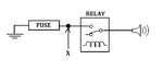
I'm working on a little project. A part of it is to connect to the car's horn.
I want to use a fuse in the way.
The problem is that in a usual use of the system I have no way to know if the fuse is burnt and it is critical.

I attached a diagram. Sorry if it is not very professional :roll:
I would like to know if the point X is connected to the ground (it will be, of course, if the fuse is ok).
I'm using arduino in the project.
How can I read point X?


thanks
 

Attachments

  • 123.png
    123.png
    11.6 KB · Views: 85

Hi,

you need to provide more detail of the wiring. Horn, a battery, a relay, Arduino... all need at least two wires. How is the arduino connected? To which GND?
Is isolation necessary?

Are you sure the fuse is in the GND wire? I think this is not usual...and not that safe as with the fuse in the positive wire.

Klaus
 

Right

The horn is the horn of the car. It is always connected to the 12v, so once you connect the ground, it beeps.
The fuse is my fuse. I connect it in the negative, because I don't touch the positive in the project. As I mentioned - it is 12v fixed. I just switch the ground to the horn.
The ground I drew is the ground of the car.

The relay is sparkfun's relay kit. This one: https://www.sparkfun.com/products/13815

I tore apart a car charger and used the circuit inside as a voltage regulator. I connect the Vin to the car battery and Vout to the arduino.
All grounds connected together.

About the project itself - to make things simpler (because everything else doesn't have to do with my question), let's say that I connect a tactile switch to a digital input and the relay's control wire to a digital output.
As long as I press the switch, the arduino output HIGH to the relay, it closes and the horn beeps.

I hope it is more understood now. Hope I can get to read the X point between the fuse and the relay.
 

GND is GND. X should not be connected to GND. If connected then fuse is of no use. Put Fuse between relay COM pin and horn. Then you can connect X to GND and fuse will work.
 

what do you mean the fuse is no use?
just to be clear - X is connected to the ground through the fuse. Not directly in any way.

My idea was that X is connected to digital input of the arduino. Then if the fuse is correct, the input reads "0". and if not - I'm not sure what happens or how to read it.

That was my idea of reading the fuse's situation. If it is not a good idea, please tell me how can I check otherwise?

thanks again
 

Read the NO pin of the Relay using a voltage divider. If horn opens then voltage will fall to 0 and you can take whatever action you need.

Another method is

You can convert current through fuse at point x using a low ohm resistor. You convert current to voltage. If horn is ON then current will be flowing and you can and need to measure the voltage when horm is ON. If fuse blows (blows only when horn is ON) then current through resistor falls to 0 and no voltage across resistor and adc value will be 0 and you can take whatever action you need.
 

that method require to active the horn.

What I would like is to check the fuse very time I restart the system. Without activating the horn.

Is that possible?
 

Yes. It is possible.

Try this circuit. It is tested. You can interface the X point to digital input pin of microcontroller. Simulation video has sound. So, turn ON speakers.

R1 is pulled-up to 5V or 3.3V.

- - - Updated - - -

Here is the circuit.
 

Attachments

  • Fuse Failure Detect.rar
    646.9 KB · Views: 100
  • Fuse Failure Detect.png
    Fuse Failure Detect.png
    22.6 KB · Views: 105
Last edited:

You can interface the X point to digital input pin of microcontroller.
You don't want to connect X to microcontroller (Arduino) input without a series resistor, otherwise the input is burned with open fuse. Proteus is pretty ignorant about this kind of elementary design faults.
 

Here is the fixed circuit. 12V - 5V = 7V drop across 72k resistor and it also limits the current.
 

Attachments

  • Fuse Failure Detect - Fixed.png
    Fuse Failure Detect - Fixed.png
    31.5 KB · Views: 117
Last edited:

Shachar85 said:
I would like to know if the point X is connected to the ground

Based on the assumptions made (horn with 12v in idle state), seems like read a single point X is not representative of the actual status of the fuse. The best approximation should be consider AND'ing the value of the variable which sets the horn with the value took from point X ( eg. (X & BUZ) ), but should pullup it to 12v, divide to reach 5v before reach uC, and add a small capacitor to supress sparks comming from relay/horn.

- - - Updated - - -

Here is the fixed circuit.

Please do not provide useless support unless you know exactly what you are doing. The above circuit would inject dirty 12v from a high inductive device directly into the point between uC and 5v. Appart from the resistors values acting at the inner clamping diodes of microcontroler I/O or some loopback control of the 5v power supply, it is a very bad practice in the field of signal integrity.
 

ok I took a closer look at the car's wiring diagram. It seems that I connected to a circuit that closes the horn's relay. Which means I didn't even connected directly to the horn's circuit.
Which means much lower currents. Which make it be safer to use without a relay at all. The original circuit don't have of the car don't have fuse there as well, so I feel pretty safe about that.

Thanks for your answers
 

It is almost universal that the car battery negative is connected to the metal body- you must not disturb that because many things will fail if the fuse fails.

It is a good habit to connect the fuse to the positive line- the horn is connected by default before the key switch. That means the horn will work without turning the ignition key on.

The horn switch is driven via a relay anyway. The idea should focus on the modularization. A simple arduino that detects a blown fuse at startup.
 

Status
Not open for further replies.

Part and Inventory Search

Welcome to EDABoard.com

Sponsor

Back
Top