Zeppelin
Member level 1
RE: RF Filter prototyping
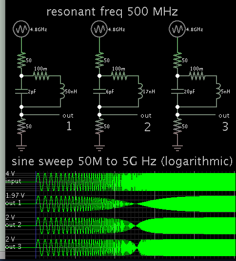
I need to make a passive band-reject filter in the 400-600MHz frequency range. I have found some design tools online, but does anyone know of any reliable prototyping method? Do I have to use surface mount components at these frequencies or can I still get away with through holes?
Thank you
I need to make a passive band-reject filter in the 400-600MHz frequency range. I have found some design tools online, but does anyone know of any reliable prototyping method? Do I have to use surface mount components at these frequencies or can I still get away with through holes?
Thank you