Continue to Site

Welcome to EDAboard.com

Welcome to our site! EDAboard.com is an international Electronics Discussion Forum focused on EDA software, circuits, schematics, books, theory, papers, asic, pld, 8051, DSP, Network, RF, Analog Design, PCB, Service Manuals... and a whole lot more! To participate you need to register. Registration is free. Click here to register now.

RC Helicopter Modding - 40MHz RC circuit

Status
Not open for further replies.

mindthomas

Member level 4
Joined
Mar 2, 2007
Messages
75
Helped
4
Reputation
8
Reaction score
4
Trophy points
1,288
Location
Denmark
Activity points
1,855
Hi everybody.
I got the idea of adding a microcontroller to an inexpensive RC helicopter to make it autonomous (hard task, I know).
I thought about different approaches to do this.
  1. Connect the microcontroller directly to the motors by an H-bridge fx
  2. Connect the microcontroller to some RC-circuitry for remote control

So I thought about going for the RC-circuitry method but I would like to know if any of you had an idea on how to make this circuit.
I have great experience with hardware and software development with low-frequency boards, but I am definitely not an analog or high-frequency guy (yet) :)

The helicopter uses 40MHz as it's carrier frequency and it has 3 channels. I don't know which protocol it uses, but how can I find out?

I'm looking forward to your answers. Thank you very much for your time in advance.


Best Regards
Thomas Jespersen
 

I once tried to make a homebrew receiver to replace the one in my R/C airplane when it flew over a ridge to parts unknown.

My lonely transmitter was 4 channel. 49Mhz. I turned it on and watched the oscilloscope. I found I didn't have to connect leads directly to the transmitter.

Somehow it picked up pulses from the transmitter, even though my oscilloscope is rated up to 1Mhz.

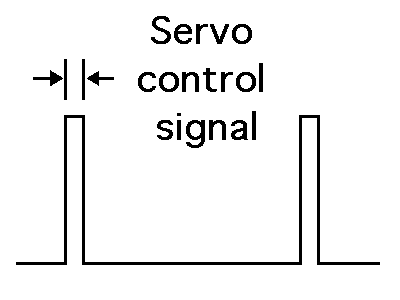
The transmitter sent a pulse train many times a second. It sent 4 pulses at a time. Each pulse was between 1 and 2 milliseconds long.

The length of the pulse is what causes the servo arm to move to a desired position.

I managed to make a simple 49 MHz RF detector and amplifier. It was based on a tank circuit consisting of a few loops of wire and a tiny value capacitor. I sent it into a 324 op amp.

The emerging pulse train was DC.

I sent it to a 4017 decade counter. It split off the pulses to separate output pins. (6 pins were unused.)

I attached a servo to each output pin. I was able to get them to work with this simple setup.

The above is only basic concepts.

It took some doing to find out how to manage signal polarity so each stage responded correctly.

I remember finding I had to add another IC or two. (Even though it adds a little more weight.)

My receiver was not too sensitive. Its range of operation was the other side of the room from the transmitter.

To extend its range would have required that I add a few stages of RF amplification. It was beyond my realm of knowledge. I didn't work on it further.
 

Thank you for your answers.
Unfortunately I'm not interested in making a receiver at the moment. But is it true that it just transmits the pulses? So how do the 3-channels work?
Could you upload an image of the measured signal, using an oscilloscope etc.?

Thank you
 

Here's a nice summary:

Radio Control Transmitters and Receivers

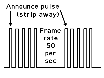
If you search on how RC receivers work you will get many hits. Right off for the lower frequencies (i.e., not 2.4 GHz), you need to distinguish PCM (pulse code modulation) from PPM (pulse position modulation). PCM is proprietary for each manufacturer. Generally receivers from one manufacturer will not work with transmitters from another manufacturer. PPM is relatively standard among brands. Some use positive shifts and others use negative shifts, but modern transmitters can be changed to work with either. Each channel is distinguished by its position within the 20 mS (typical) repeat frame. Different brand receivers will work with a single transmitter. I suspect what you have is PPM.

Control input is reflected by the pulse width for the appropriate pulse within that repeat frame. A pulse width of 1.5 mS generally means to center the servo. The range is 1.0 to 2.0 mS gives the extremes of servo motion. There is quite a bit if flexibility -- many transmitters allow ±125% of the above pulse widths.

In finding the above reference, I came across something that might be even more on point for your goal of interfacing with an MCU.

Interface to a RC Reciever

John
 

is it true that it just transmits the pulses? So how do the 3-channels work?
Could you upload an image of the measured signal, using an oscilloscope etc.?

Just dug out my notes made 10 years ago.

For sake of accuracy, the control signals are 'off' periods in the RF carrier coming from the transmitter.

The receiver converts these gaps into pulses. My transmitter was 4 channel. It broadcast an ANNOUNCE pulse followed by 4 more pulses. 50 frames per second.

7_1316992865.gif


The receiver breaks up the pulse train. It must handle as many channels as the transmitter sends (or maybe the receiver will simply ignore any leftover pulses).

It distributes a pulse to each servo. The width of the pulse tells the servo where to move to.

25_1316992865.gif


One channel is usually dedicated to motor throttle. Look for a stick on the transmitter that stays where you put it (rather than return to center like the others). The receiver sends this signal to the motor.

Each servo acts independently. Each servo's range of action must be properly adjusted for the aircraft to fly properly.

There are transmitters that 'mix' the stick inputs according to what kind of aircraft you're controlling. (V-tail, etc.)

It's up to the pilot on the ground to work the sticks right. To control an aircraft automatically will require a very intelligently programmed microcontroller.
 

Thank you BradtheRad.
I will try to probe the signal, to see if it is using the same technique as you described. I should be able to see the variations in the pulse train when changing the knobs.

Best Regards
Thomas Jespersen
 

Status
Not open for further replies.

Part and Inventory Search

Welcome to EDABoard.com

Sponsor

Back
Top