Continue to Site

Welcome to EDAboard.com

Welcome to our site! EDAboard.com is an international Electronics Discussion Forum focused on EDA software, circuits, schematics, books, theory, papers, asic, pld, 8051, DSP, Network, RF, Analog Design, PCB, Service Manuals... and a whole lot more! To participate you need to register. Registration is free. Click here to register now.

RC Filter Concepts help.

Status
Not open for further replies.

DanielB33

Newbie level 3
Joined
Nov 23, 2012
Messages
4
Helped
0
Reputation
0
Reaction score
0
Trophy points
1,281
Activity points
1,318
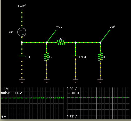
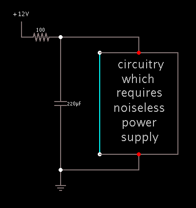
I was told to add a RC filter in front of my op amp by my boss, I originally just had a capacitor at the power input. I do not understand the significant difference between having the resistance and not. If I have a low pass filter, from my point of view all it does is make sure that ripples or noise from my supply does not cause the capacitor to supply to power supply with current rather than the op amp. How does the resistor make a difference and what differenceS does the R make???

ALSO, I understand that adding impedance to the low impedance power input...well, adds impedance. But How does adding this resistor/impedance with the cap cause noise reduction?

For me to really understand this, I need to be able to visualize the differences between the following:
what will happen if I only use a capacitor at the input verses
what will happen if only use a resistor verses
what will happen if I use a rc filter configuration

Thanks much for you help.
 

Is there a chance your boss meant this kind of arrangement?

3133851700_1353721157.png


Suppose the power supply has noise on the lines. You have circuitry which is easily affected by such noise. Adding the resistor provides a degree of isolation. It allows the smoothing capacitor to do its filtering job a little better.

If the boss thought you should add a resistor parallel to the load, then I agree with your view that it is of dubious value. It will draw away current more quickly, causing greater ripple voltage on the supply.
 

i am also interest in the answer :)

- - - Updated - - -

regarding the filter it is low pass filter designed to supress any noise above the corner frequency of the filter which selected according to our circuit. it is important to consider that since the resistance is in series with the supply rail it will have a voltage drop and thus reduces the output voltage, this becomes more significant if the load current is high as well the capacitor, if the supply voltage is small this become worse

for a single capacitor in parallel with the supply it will also lead to decrease the noise effect and it is usually put in front of the bridge rectifier to make the output a little like constant

when we use the RC filter or the capacitor I also have no exact answer
 

Yes, the isolating resistor causes a drop in voltage. Its value must not be so high that it causes too much drop.

This screenshot shows the effect.


A 1V square wave was added to the 10 VDC supply, in order to simulate noise on the supply rail.

The 1000 uF capacitor does not filter the noise very much.
By installing a low ohm resistor, it creates an isolated section allowing a smaller capacitor to have much more smoothing effect.
 

The resistor mentioned lowers the cutoff frequency of the lowpass filter. Lower cutoff frequency provides more clean DC. Think about a simple RC lowpass filter, its cutoff frequency is 1/(2piRC). On the other hand, you loose enery on the resistor, it is a trade off, I did not encounter any resistors in DC supply filters.
 

now the question is still the same, why some designers use only large capacitor in parallel and they dont use the low pass filter?
 

To answer the question you would want to add "noise" (interference) sources to your model. In any case, they'll expose some source impedance. I guess you'll see why a simple capacitor already has a filtering effect. If you consider load current transients of other deviced connected to the supply rail, they can be modelled as current sources in a first order. Bypass capacitors are placed to reduce the voltage drop caused by this current transients.
 

Status
Not open for further replies.

Similar threads

Part and Inventory Search

Welcome to EDABoard.com

Sponsor

Back
Top