Continue to Site

Welcome to EDAboard.com

Welcome to our site! EDAboard.com is an international Electronics Discussion Forum focused on EDA software, circuits, schematics, books, theory, papers, asic, pld, 8051, DSP, Network, RF, Analog Design, PCB, Service Manuals... and a whole lot more! To participate you need to register. Registration is free. Click here to register now.

RB0 Interrupt Handling Using PIC16F877A

Status
Not open for further replies.

Mexpost

Newbie level 4
Joined
Dec 14, 2012
Messages
7
Helped
0
Reputation
0
Reaction score
0
Trophy points
1,281
Location
Monterrey
Activity points
1,458
RB0/INT pin Interrupt Handling Using PIC16F877A

Hello world; I just joined this forum in hope of learning something important ... just starting and learning the hard way (no emulation software yet) .


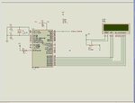
Q: If I program an interrupt service routine to respond to an external generated high input on the RB0/INT pin, can I use this pin *as an input* if PORTB already has an LCD displaying the time continually refreshed by the 877A? I am using higher numbered RB outputs and PORTB is configured in the main program as the LCD 1602 output, but RBO/INT can be made an unused pin since only six of the eight (RB0, ..., RB7) are necessary and the Lcd can go on 2-7, for example. I've got a lot to go to get a better feel for this, but if the main program generally uses PORTB as an output (LCD refreshes fast in a while(1) loop).

Can my routine use the unused RB0/INT pin on the 16f877A to detect an input signal and would I make PORTB an input inside the "ISR"? Or is this all wrong. I don't want to try it since writing code is difficult for me at this stage to chase something wrong, and then I don't want to risk applying 5V to RBO//INT for fear of a problem with the MCU or LCD. It's ok in my project if the LCD display skips a little when the interrupt happens, as long as it goes back to continue to update time in the display after the interrupt 'returns'. OK, please, anyone (like Tahmid if he is here because I saw some advice he gave on 877A interrupts) who can give me some appreciated help?

Thanks
Mex
 
Last edited:

Hi,

In a word, yes it would be possible, however you will need to go though your lcd routine as they often change RB0 from input to output along with the other PortB pins.
You need to have RB0 totally free of the lcd routine and any TRIS instruction it may use.

You need to show the lcd code you are using.

On a 40 pin chip like that its generally better to use PortD for the lcd so you can uses PortBs extra features without the problems you have now.


You would normally initially set up all your ports in your main code, though you can change them anywhere.
 
  • Like
Reactions: Mexpost

    Mexpost

    Points: 2
    Helpful Answer Positive Rating
Hello wp and thanks for the tips,

The LCD code is as small as I can imagine, but the problem I worry about is what you said in the first two main program instructions here. I checked and PORTD looks doable although as I said I am just starting this and it is complicated at first glance to learn both logic and language (so I really appreciate the tips). But it's very important to me since I work 24 hours caring for my bedridden and paralized parent. sometimes there is no time to rest. The project is intended to assist me in the care situation and maybe give me a chance to have uninterrupted sleep for three whole hours by monitoring some things that require :) interrupting me out of "personal sleep mode" to service upon need :-( Some of the multipurpose PORTC pins (BTW) are used with the time from the RTC chip, but I need to see if I can change this over to PORTD as you suggest. Still. the project isn't finished and testing as I improve it and will need more additions, so this is very important for me to know in case I end up using PORTD for something else.

The definitions relevent are:

sbit LCD_RS at RB2_bit;
sbit LCD_EN at RB3_bit;
sbit LCD_D4 at RB4_bit;
sbit LCD_D5 at RB5_bit;
sbit LCD_D6 at RB6_bit;
sbit LCD_D7 at RB7_bit;

sbit LCD_RS_Direction at TRISB2_bit;
sbit LCD_EN_Direction at TRISB3_bit;
sbit LCD_D4_Direction at TRISB4_bit;
sbit LCD_D5_Direction at TRISB5_bit;
sbit LCD_D6_Direction at TRISB6_bit;
sbit LCD_D7_Direction at TRISB7_bit;

and the main program's relevent code is:

PORTB = 0;
TRISB = 0;
TRISC = 0xFF;
LCD_Init();
LCD_Cmd(_LCD_CLEAR);
LCD_Cmd(_LCD_CURSOR_OFF);
LCD_Out(1, 1, "TIME: ");
LCD_Out(2, 1, "TODAY: ");

…this intermediate part omitted because it only is manipulation to construct the displaying of current time (ctime) and current date (cdate) char strings)…

LCD_Out(1,7,ctime);
LCD_Out(2,8,cdate);
Delay_ms(50);

One other thing - Maybe it is in plain sight in the datasheet but I didn't see it: do I have to apply the Vdd (~+5V) to the interrupt pin RB0 or is it possible to input up a different voltage, probably less (between 3.3 and 5) but might be a little more, from another part of the circuit with not a perfectly controlled output where my signal interrupt is generated. In that case what would someone normally do, put a regulator, or use a transistor to switch directly from the V+ rail, or something else?

thanks for this!!!
 
Last edited:

Hi,

Afraid I do not know that code as such, but looking at those individual bit definitions I would change them to Port D and also set PortD/TrisD to 0.
Bet it would work, cannot really harm anything trying.

Equally, you might find that you can just change RB0 to Input without it affecting the lcd, again give it a try.

I doubt you will ever want to use PortD for anything other than digital i/o whereas PortB and C have many useful extra functions.

For an input to RB0 or any other port best try and stick to the same +5v as the rest of the circuit.
An example of how to connect a simple switch is in this good tutorial **broken link removed**

If you want very different voltages put up another post saying exactly what voltage is coming in and from what.

Don't forget the the 877a chip must have both Vdd and both Vss pins connected; plus pin 1, Mclre, must be tied to Vdd via a 10k resistor.

If the Lcd idea on portD does not work and no one else comes in, put up a new post about it to get their attention, BigDogGuru is usually on the late shift !
( though he might be busy watching the aftermath of that terrible school massacre)
 
  • Like
Reactions: Mexpost

    Mexpost

    Points: 2
    Helpful Answer Positive Rating
Hi wp

Thanks for the switches reference since it also has some basic interrupt things that are well written for even me to understand. It will take me a while so I won't be on a Big Dog Safari this evening; everything I do is in tiny spurts and I never can concentrate because of the situation I mentioned, very nerve racking to try and write and study ... hence the serious need of this project and me diving into MCUs shamelessly since what I want is tailor made and this is the only way (without having a treasury).

I am working on the code and breadboard modifications to translate to PORTD and add a simple interrupt version I can test by touching a dangling wire off the Vdd rail to RBO.

Oh, I did manage to google up an answer somewhat about the voltage, here it is in case you or anyone in here is curious. There is approx a 1V tolerance, so to set low we can be up to about 1V and to set high we can be as low as 4V. I'd put the link but duty is calling and it's misplaced for the moment.

Thanks for the basic power connections, that is about my level two days ago, now I'm trying for the next steps and really appreciate any of this priceless free advice, great bunch here (especially you for answering!)
Mex
 

Hi,

Couple of things that might help, your use of a breadboard, they are generally ok but unless really clean contacts they can give odd problems.
The crystal and its caps usually have very thin leads and they can looose contact with the breadboard.
Its often better to solder the crystal and caps to a little bit of strip board and then have three short, thicker wires to plug into the breadboard.

About you RB0 input, touching the wire may seems to work but its not a good idea, its sounds like you have left pin RB0 'floating' , nothing connected to it, so its constantly in a flux between high and low.
You should use a pullup or pull down resistor as shown in the diagram.
Also using you finger is not a good idea without the relevant circuitry as you could easily discharge static into the pic and destroy it.

Yes, the input voltage can be lower that +5v, but i did not want to complicate things, though its important another voltage source is connected correctly and to the same common ground/ 0v.
Without knowing what you are connecting up , its hard to say whats really needed.
 

Attachments

  • ScreenShot004.jpg
    ScreenShot004.jpg
    62.8 KB · Views: 119
Thanks wp

So I don't stray from the subject for others (although the truth is a single subject thread isn't nearly enough first aid for this), first on the interrupt RB0 pin comment. Coincidentally, I do have exactly a 10KΩ resistor to Vdd on RB0, and honestly I didn't have a reason except to have seen one on someone else's diagram somewhere which had nothing to do with my circuit but I was a bit uneasy, so that's great reassurement. Will that handle the static issue though? I am pretty careful but accidents happen. The wire I had in mind is insulated so probably I wouldn't touch it. I could add a dangling wire to the circuit, from the breadboard negative rail and hold it to ground myself when I use the improvised dangling hot wire to touch the RB0. The whole breadboard things are provisional and as time permits, and urgently I need to finish this up and see if I can etch a simple PCB with all the fancy Eagle software which is another sensitive point to learn. Regarding grounding, I think I'm already somewhated grounded to the breadboards because on the other breadboard, the first of the future interrupt signal generators, very sensitive, when I sit on my leg or skin touches the chair and then touch the breadboard about 1mA current flows through me from it. So you're right to remind me to be careful!

Here is what I plan to do about the interrupt signal which from me lets call it an unreliable voltage when I need to get say something between 4.5V - 5.3V or so reliably. I think I can master wiring in a 555 'timer' to lock me in a single, clean (and unbouncy) signal for the interrupt and I won't even need to worry about software delays. My problem wasn't contact bounce, the signal is generated is ok, but at the threshhold it ramps instead of being a clean step. This gets me wondering if instead of RB0, whether the Analog input to the 877A could be used for an interrupt (or simply to call a subroutine, either way, there is no need to actually interrupt displaying the time, just to add an additional little note to the LCD and whistle for me to come running) routine somehow: if signal>X mV, then ring alarm and print current time, current date, and interrupt time.

Thanks for the picture, it felt good to see it strangely giving me confidence, after seeing other people's ideas like this, but never my exact case. Still, the chip will remain a black box for a while ;-) Now the compiling for interrupt has me all screwy because it is telling me the bcd and other conversion/reading functions can't be called both from the main program and from the interrupt. Pity. Now I guess it is back to the drawing board to make duplicate functions (eg. "bcd2char" and "bcd2charprime") to be used in their respective routines. That *is* a 'bummer', but if I'm to trust MikroC's compilation complaining, a necessary part of the programming logic.

Now, for the unrelated to interrupt comment, but very relevant comment you had on breadboards. First, I have two crystals on the MCU breadboard and the time it is keeping is incredibly good from what I've read. It gains only 1.5 seconds per day! But there is a thing to be learned the hard way. I though my soldering of the header on the LCD display was to blame and was bending the heck out of it to get the display to resume time. So that is where my screwy breadboard behavior is, but after trial and error, it was not the soldering, but suspicious connection to the "enable" wire from breadboard to LCD. But after hairpulling it was not that either although it masqueraded as so. The only thing that gets a reliable kick to resume refreshing the LCD is holding the breadboard by the corners and giving it a tiny 'twist' pressure. I guess this is what you mean by "odd problems"!!!! Since it is only for project development, I'm living with it and the twist until I can get the project off the train wheels (breadboard) and on the pcb...

Thanks again, I'll be back whenever the time permits, though the situation has become very difficult in recent hours, I know everyone has their projects, but in my case each interruption is to save my parent's life and it has a chilling effect to come back and try to pick up where I leave off, but leave one eyeball behind to keep watch. BTW, the project detects these epidoses so each interrupt is a lifesaving emergency. The project certainly won't guarantee anything, nd could never be a commercial project due to liability concerns, but it is much better than me dozing off and not having a backup to alert me. This may be my first µC project but it will always be very, very dear. The hope is I can actually finish and implement it for some of the remaining time.

Thanks again and be back when I can
Mex
 
Last edited:

Hi,

Think I can see a little more what you are trying to do with the whole project.

However I think you have a serious design flaw.

It sounds as if you are connecting your patients to a Pic, but the problem with the Pic is that any input lead is very prone to electrical pick up / interference that can send the pic chips hardware or softwre crashing.
Long leads, over a meter, just make the problem worse.

You need to say what distances you are talking about.

Consider some modified way of doing it, so that the incoming wires are isolated by an optocoupler or reed relay just by the pics input pin.
This will also act as a 'clean' switch to feed RB0, though if thats all the program is doing you can just monitor any pin.

You can use in RA4 for input as that has a Schmitt Trigger type of circiut that will clean things up, or you can buy opto couplers with Schmitt trigger built in.
 
  • Like
Reactions: Mexpost

    Mexpost

    Points: 2
    Helpful Answer Positive Rating
Thanks wp, sorry about the delay - in my situation things can completely occupy me around the clock when it goes bad, or I'd have been back sooner.

- I'd like to stick with an interrupt since that is how I initially thought of this. Later I'll worry about how to do it on other input types but it's good to know that option exists, so thanks for the response.

- OK, the circuit is set up on PORTD for the LCD and functions perfectly, in the hardware on the breadboard; It's better than before, no more board twisting to make some unknown critical connection to kick start it again so there was even that benefit to rewiring some. There are only 6 connections necessary from the LCD module to µC PIC chip.

- My problem I need to focus upon is the interrupt code. The situation for care giving is overwhelming and prevents my normal self going off on a million tangents I find interesting. Under the circumstances, unfortunately having that priviledge is not feasible if I have any hope to finish soon. Here's where I'm at and in sore need of help... I have two program versions. One working like before with LCD on PORTD. The other with this additional interrupt code which caused a failure and only seems to make it up to leaving the LCD initialized. Here is the very basic code and it is where I really need help since I still can't quite get my arms around interrupt coding.

I have this in the beginning of my main program, before it enters another while(1) loop for continually updating the LCD's correct time:


Code C - [expand]
1
2
3
4
5
6
7
8
9
TRISB = 0x01;
    INTCON.GIE = 1;
    INTCON.INTE = 1;
    INTCON.PEIE = 0;
    OPTION_REG.INTEDG = 1;
    while(1)
      {
     table[0] = '0';
       }


My understanding (which may be wrong) is that an infinite loop must follow the initialization of the interrupts in the main program, although I don’t quite get how, if executed sequentially (or is while work in parallel with the rest of the code?) it will get beyond there executing through the code … table[0] is just some chance character I have defined which is constant,and I thought it best to put something inside the while(1). Then I have this exact code in my tiny interrupt routine which is in the last lines of code following the main program:


Code C - [expand]
1
2
3
4
5
6
7
8
9
10
void interrupt(void) 
{ //RBO/INT Interrupt
 
      if(INTCON.INTF == 1)
           {
             flag=1;
             INTCON.INTF = 0;
            }
 
 }


Can you see any problems? All I need is for the 16f877A ISR-related-code to set an integer = 1 which I named flag, and then go back to work in the main program.

- On the suspected design flaw and distances, etc. All the electronics is going inside a (4x6x3 inch) 10x15x7.5 cm project box, from 4 breadboards I can't wait to pull apart, and my analog circuit we can call the 'sensor' or really 'sensorplus' has actually very clean output. I'm sure I didn't give that impression or maybe exaggerated a bit - when I should have explained better especially to be respectful to anyone kind to help. The comments I made about the signal should have been (a little embarrassingly) that my sensor circuit has a great signal capability except really I didn't want to deal with adjusting it since it was a big time sink already, and I have it running around 4V. It's actually quite stable and very clean and decoupled from the 'probe' part. It was quite complicated for me since before this foray into PIC, that was actually going to be the project,. I realized I wanted to record the times of the events - and that little detail forced me into the uC world. If there is a design flaw it is that the PIC is only being used as a RTC event recorder and my 'sensor' circuit actually uses analog logic to flip a few relays/alarms, when the PIC could have done this more easily had I begun with it. To be bluntly honest, I learned the 'electronics' for the 'sensorplus' circuit (initially envisioning the project in analog) oblivious to realizing the easy of ability for me to create a MCU based project; I didn't know the difference between analog and digital electronics initially. For that matter, I wasn't aware that I could get one of these nifty programmers and program my own smart chip... 'nuff said...I've progressed since then. As for optocouplers, they are probably not necessary although it certainly is another option to connect to the PIC (and I've got three different type some in use already, but all performing analog circuit functions).

Anyway, can you kindly help me clean up the interrupt code so it actually services by setting my integer 'flag = 1' when being serviced?

Thanks!!!
Mex
 
Last edited:

OK, I managed to figure myself the most elementary interrupt service routine coding I needed. In case anyone wants to see how this works here is the correct code:

For the interrupt subroutine:


Code C - [expand]
1
2
3
4
5
6
7
8
9
10
void interrupt()
 { //Interrupt for detected 5V signal to RB0/INT pin 33 of PIC16f877A
 
      if(INTCON.INTF == 1)
           {
            flag=1;
             }
      INTCON.INTF = 0; //Clear the interrupt condition
 
 }


in the main program:


Code C - [expand]
1
2
3
4
5
6
7
8
9
10
11
12
13
14
15
16
17
18
19
TRISB = 0x01; //use PORTB input
    INTCON.GIE = 1; //Enable Global Interrupt
    INTCON.INTE = 1; //Enable RB0/INT external Interrupt
    INTCON.PEIE = 0; //Disable all unmasked peripheral interrupt
    OPTION_REG.INTEDG = 1; //Interrupt on rising edge (0 is falling edge)
 
...
//other code in main program...
...
if(flag == 1)
                {
                   ++eventcounter; //if you want to count the number of interruptions that accumulate
                   //put your other manipulations here related to the processing of the interrupt event
                   flag = 0;//clear your flag so you can service to the next event
                   }
          else
              { //put here anything done when the interrupt is not in effect
                   flag = 0;//you can clear the flag but this line is probably unnecessary since only flag=0 gets here
                }


How simple it turned out ;-) no while(1) loop necessary...(it was my problem but never quite made sense)

As for the phasing in of my input signal, I ramped up the voltage in my sensor to about 5.3V, put in a diode inline on the hot signal to drop it between 4.5V and 5V on the low side since the supply may vary over time and I don't trust due to the power supply. Then, for the signal it generates, I could then use a voltage regulator IC instead, but really not a good option since I really don't want the sensor operating too high either and they require greater inputs. Optocoupler, as mentioned is another possibility. But I tested already and the signal is clean, so I am just connecting it directly to RB0 and looking for an appropriate zener diode additionally to short the minor signal excess voltage but more importantly should the supply fail a little, my PIC will be ok. I think it will be 5.1V Zener from signal into common ground of sensor and PIC circuit. Not many signals occur in a day and they are of short duration, so this seems like a good solution.
Mex
 
Last edited:

Status
Not open for further replies.

Similar threads

Part and Inventory Search

Welcome to EDABoard.com

Sponsor

Back
Top