Continue to Site

Welcome to EDAboard.com

Welcome to our site! EDAboard.com is an international Electronics Discussion Forum focused on EDA software, circuits, schematics, books, theory, papers, asic, pld, 8051, DSP, Network, RF, Analog Design, PCB, Service Manuals... and a whole lot more! To participate you need to register. Registration is free. Click here to register now.

[SOLVED] Radon detector : Problem with 50Hz noise from 200V DC PSU

Status
Not open for further replies.

sinnadyr

Member level 2
Joined
Nov 11, 2010
Messages
51
Helped
0
Reputation
0
Reaction score
0
Trophy points
1,286
Activity points
1,608
Hi there guys and gals!

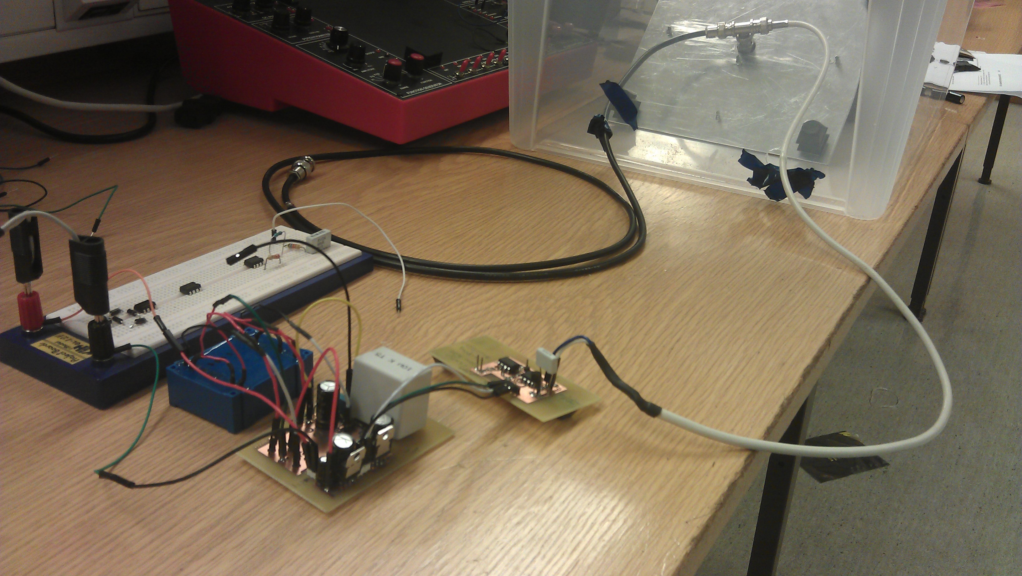
Me and my class mates are making a radon detector and have made PSU, charge and shape amplifier, peak detector, LabVIEW and AVR application and are soooo close to the finish, but still so far away.
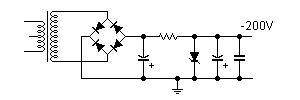
Our PSU is powered by a 17.5V AC adapter (not grounded), transformed up and rectified to 210V DC. This is to get good measurements from our silicon diode detector. The problem is that we do not have a very good lab environment, and is clearly bothered with 50Hz (magnetic?) noise. This ripple is not that big, but is amplified through our circuit and drowns the detector signal, which is only at a few millivolts.

On the PSU output we have a 10µF smoothing capacitor in parrallel to ground, but this does not seem to do the work. Does anyone have any tricks on this?
powersupplydesign.png
The lower circuit is for powering +/- 5V opamps. The upper part is the PSU that supplies negative 200V.

Any help would be REALLY appreciated! Thanks in advance.

EDIT: Since the +200V is connected to ground to get -200V, may this be a problem? This ground follows the rest of the circuit as 0V reference...
 
Last edited:

I get an error message when I try to view your attachment: "Invalid Attachment specified. If you followed a valid link, please notify the administrator"
 

It is fixed, something was wrong with the upload.
 

Concerning the 50 Hz hum, the problems may be more than one.
1. You mentioned that your 17.5 V AC wall transformer output is floating, not grounded. Its AC line may carry external interference, from fluorescent lights, etc.
2. As you generate several DC voltages, including 200 V DC, please take care in checking good filtering circuits. I would advise to use integrated voltage regulators like LM317T- its voltage range can be extended, or use discrete transistors for it. Centuries ago, I used gas-discharge voltage regulators, to regulate 85, 100, up to 450 V. And resistor- capacitor filters to reduce hum and noise.
3. As your signal circuits seem to amplify the annoying 50 Hz hum, you can try to modulate the 200 V voltage e.g. by `1 kHz, then use a selective 1 kHz amplifier to separate your desired signal from noise.
4. Please take care in a good shielding! Diode detectors are sensitive to light, RF and many other things, in addition to be good gamma-ray detectors.
 
We were "forced" to use some of the equipment, included the ungrounded AC adapter, and weve been thinking that this may cause a major source of interference (since turning the light, fluorescent that is, on and off influenced our circuit).
But since the 200V is grounded, and this ground signal is carried through to the rest of the amplifier circuits, may this be a problem? We just could not figure out another way to turn the voltage negative. Unfortunately, the time is running out and a total redesign may take longer time than we have left...
 

First in a case like yours, try to find out the cause of interference. If you connect an oscilloscope to your signal output, what is the shape of the interfering signal? If it is a round sinusoid, then it comes from a poor filtering of the DC rectifier. Your schematic show 10 uF, maybe 470 uF is what I would try. Also add a 0.1 uF capacitor in parallel. Using only one 200 V Zener may be not good enough, HV Zeners are "round" and do not smooth the DC output. Try to find an old-style gas-discharge voltage regulator, or, use e.g. 3-4 neon lamps (from AC switches, etc.) to improve the regulation.

If the pulses are square, they may come from the lights around, a SCR dimmer, or similar devices. Take care that your gamma-ray diode cannot see the light or AC signals from surrounding devices.
As the signal output may be DC or pulsed, try adjusting amplifier gain ; the first stage may be overdriven by the interference.
Good luck!

---------- Post added at 18:42 ---------- Previous post was at 18:36 ----------

The neon lamps "regulate" around 70 V each, so connect them in series, and use instead of the Zener, or in parallel to it. You can also use a biased LM317T voltage regulator. I saw Motorola HV integrated regulators , MC1466L, for up to 500 V DC.
 
Thank you for your answers jiripolivka!

Unfortunately, it's past bed time here in Norway, and we don't have access to any high voltage capacitors, only 50V. Is it possible to connect any of them in series to increase the voltage rating?
The noise is sinusoidal, and somewhat round. Old gas-discharge regulators is something we've never heard of, but we will look in to it. Why is it that neon lamps would work for smoothing? The alpha-detector diode is covered with cloth, and (hopefully) doesn't see the lights surrounding it.

For the good luck part: thank you ;)
 

Have you verified that the interfering signal is 50Hz and not 100Hz? And why the orientation of the -200V supply? Hard to be sure if it's at the root of your problem, but I suggest you ground the +ve output of the rectifier and move R1 to the negative side. That will at least eliminate that as a possible reason.

As jiripolivka pointed out, it's possible that the AC supply is carrying some RF interference. I suggest paralleling D1-D4 with capacitors of around 0.01uF of suitable voltage ratings.
 

[/COLOR]The neon lamps "regulate" around 70 V each, so connect them in series, and use instead of the Zener, or in parallel to it. You can also use a biased LM317T voltage regulator. I saw Motorola HV integrated regulators , MC1466L, for up to 500 V DC.
Aha! Was not aware of that, but will try it if we get our hands one some.
 

Have you verified that the interfering signal is 50Hz and not 100Hz? And why the orientation of the -200V supply? Hard to be sure if it's at the root of your problem, but I suggest you ground the +ve output of the rectifier and move R1 to the negative side. That will at least eliminate that as a possible reason.

As jiripolivka pointed out, it's possible that the AC supply is carrying some RF interference. I suggest paralleling D1-D4 with capacitors of around 0.01uF of suitable voltage ratings.
Well, when you mention it, it is the 100Hz which is the main problem in our circuit, any ideas why? We though maybe the 100Hz derived from the 50Hz in some way.
About the negative bias: The detector needs a negative bias to not break down the diode. Since the alpha-particles are positive we need negative 200V.
chamber scetch.png
 

I would try to check any TV repairman, the old TV sets used 100 uF capacitors rated to 350 V. You can connect ellytic capacitors in series but add in parallel to each a 100 kOhm resistor to divide the high voltAge reliably. And I would test the series-connected capacitors through a 10 kOhm resistor from your HV rectifier, and connect a DVM to each, to monitor that its breakdown voltage is not exceeded. Many ellyts do leak.
Gas-discharge tubes connected with a series resistor to a higher-than-breakdown voltage have a "flat-voltage" region used for regulation. Since 1920s there were many voltage regulators using neon lamps, I know those made in Germany. They were very reliable, no heater, long life. Maybe some old radio hams like me keep them in their collections.

As you are using a HV Zener in your circuit, maybe you can get more and test which regulates best. From several Zeners, you can find one with a higher voltage, and cascade two regulators, with a 500 Ohm resistor each.
I would start with adding capacitors, before and after the Zener regulator. As the 50 Hz "noise" is a round voltage as you said, filtering is the problem.
Also, your rectifier is full-wave type, so the hum should rather be 100 Hz. If 50 Hz prevails, try to replace the rectifier diodes, one may be faulty.
Try also to add ceramic 10 nF capacitors from the AC 16V lines , to your ground, maybe also across transformer secondary. In HV rectifiers, it can be also good to add 10 nF, 500 V capacitors across each diode.

As you write that your diode is covered by cloth, please try to cover it with an aluminum foil, so no light can reach it. At the diode your low-level signal starts, so be sure you amplify only what you want to amplify.
 

As you write that your diode is covered by cloth, please try to cover it with an aluminum foil, so no light can reach it. At the diode your low-level signal starts, so be sure you amplify only what you want to amplify.
But then no radon gas will enter the detector chamber, but maybe we can try covering the box containing the detector with alu. foil.
We will try extra filtering, and thank you both for so much help! If any ideas comes to mind, please keep posting them.

Thank you!
 

Well, when you mention it, it is the 100Hz which is the main problem in our circuit, any ideas why? We though maybe the 100Hz derived from the 50Hz in some way.
Yes, it's derived from the 50Hz mains frequency. But the fact that it's 100Hz implies that the source of the interfering signal is the rectified power supply ripple rather than direct mains. That narrows down the possibilities.
About the negative bias: The detector needs a negative bias to not break down the diode. Since the alpha-particles are positive we need negative 200V.
I understood that. I was not suggesting that you use a positive supply. You can get a negative supply with this arrangement:

14_1323887349.png
 
Last edited:
Wow, is it that easy? Amazing! But... don't we also need to arrange the electrolytes the other way?
Thank you so much!
 

Yes, the electrolytic caps have to be inverted. In fact, I spotted the error and edited my post with a corrected diagram before you replied, but I got disconnected and could not upload the corrected schematic for a few minutes. It's done now.
 
Last edited:
Well, some kind of breakthrough went down just now. As you said Pjdd, covering up the sensor was one of the keys on our way to the sollution. By turning of the lights or covering the sensor even better, the 100Hz disappeared almost completely, but the 50Hz still survives. We still get 50Hz about 75mV, and it is still there if we disconnect the 200V from the detector. We would rather not connect any capacitor on the output of our detector, since our charge sensitive amplifier is very accurately designed due to parasitic capasitances and trying to maintain as low noise as possible.
Adding the schematic for the charge amplifer:
charge_amp.png

And suddenly our 5V +/- regulators got REALLY hot, so we need to look in to that as well.
 

Glad to hear that you're making progress. Actually it was jiripolivka who brought up the matter of shielding it from ambient light. The idea occurred to me too but it was he who mentioned it first.

If the 100Hz shows up again, assuming that it's from the -200V supply, it can be further suppressed with a modification of the filtering circuit.

As to the 50Hz, that's probably picked up from stray EM fields. Keep all wires and component leads as short as possible. If you use a length of wire to connect the detector diode to the amplifier input, use shielded wire and ground the shield near the amplifier input.

Regarding heating of the 5V regulators, what loads do they supply and what are the currents involved? Also remember to place the 0.1uF caps at the outputs as close to the regulators as possible. Another thing is that most negative regulators like the 7905 need a higher value of low-ESR capacitor than a positive regulator at the output. 0.1uF may not be enough to prevent instability. It's best if you use at least 0.47uF. Tantalum caps are fine. The 470uF electrolytics have too much parasitic components to do the job.
 

We think that the 50Hz is EM fields as well...
This is our connected sensor, -200V bias on the black wire, signal out from the detector on white wire:

And as you can see from this next picture, the cables are fairly long, so as you say, we should try to get ur hands on some shorter cables. Both cables are grounded in both ends.


Just wondering if the cables could be screened in some other way, on top of being screened cables.
 

You mention that covering the diode from light improved things;
ambient light will carry power line (2X) flicker and bother any
exposed junction device.

Your radon detector is really picking up transient charge from
alpha particles/ These are very short duration (at the device
level) and high pass filtering from the detector, along with a
minimal detector self- and output capacitance are good ideas.
An avalanche detector will give you charge gain at the cost
of some complexity in biasing (the -200V).

But there are quite a few very alpha sensitive ICs out there
which might serve as detectors. People use DRAMs (you'd
de-lid I expect) for their large sensitive area and simple
digital functionality at low cost.
 

Status
Not open for further replies.

Similar threads

Part and Inventory Search

Welcome to EDABoard.com

Sponsor

Back
Top