Continue to Site

Welcome to EDAboard.com

Welcome to our site! EDAboard.com is an international Electronics Discussion Forum focused on EDA software, circuits, schematics, books, theory, papers, asic, pld, 8051, DSP, Network, RF, Analog Design, PCB, Service Manuals... and a whole lot more! To participate you need to register. Registration is free. Click here to register now.

RadioShack 13.8v/3A power supply transistor ID/replacement.

Status
Not open for further replies.

Klondike Mike

Newbie level 4
Joined
Sep 8, 2010
Messages
6
Helped
0
Reputation
0
Reaction score
0
Trophy points
1,281
Location
edmonton
Activity points
1,334
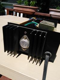
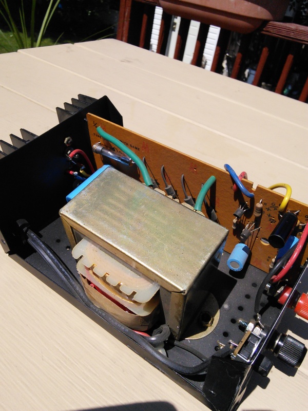
Can anyone suggest a replacement transistor? This 13.8v power supply (RadioShack) blew up on me many years ago and I have been dragging it around knowing someday I would repair it. Well, this weekend I finally got around to popping the cover on it. Blown fuse, replaced. Checked main electrolytic capacitor, suprized that it checked OK. Looks like the power transistor is shorted though. Can't seem to find ANY data on a DVE 312 or a cross reference. This power supply seems to have been common with many other brand names. Any suggestions on a replacement for the DVE 312?


Last edited by a moderator:

Almost certainly the replacement type will be a 2N3055. I can't be certain without tracing the rest of the circuit but most of these PSUs were simple regulator circuits without feedback or overload protection. The 2N3055 is a good bet and very easily available.

Brian.
 
Almost certainly the replacement type will be a 2N3055. I can't be certain without tracing the rest of the circuit but most of these PSUs were simple regulator circuits without feedback or overload protection. The 2N3055 is a good bet and very easily available.Brian.
Woo-Hoo! 2N3055 ordered on eBay. Thanks Brian.
 

Ditto the 3055. The circuit should be around somewhere too. Perhaps rejig it to match https://bama.edebris.com/manuals/radioshack/22-504
Thanks for the schematic. I have a number of various 13v power supplies that I was evaluating over the weekend. This one was broken. Another was poorly regulated. As mentioned, I did order a 5 pack of 2N3055's to repair this one. I also found this inexpensive module that I probably could use for both.


https://www.ebay.com/itm/150W-DC-DC-Boost-Converter-10-32V-to-12-35V-6A-Step-Up-Adjustable-Power-Module-/171219013561?hash=item27dd72cfb9:g:MoYAAOSw-W5UtIiu
 
Last edited by a moderator:

Caution: That's a boost converter, although it might work, you really want a regulator to drop the voltage from the transformer.

You would have to keep the transformer, rectifiers and reservoir capacitor so you have a DC voltage ahead of the regulator but typically it would be around 18V, dropping to about 14V under full load. The original regulator turned excess voltage and current into heat, you can do it more efficiently with a switch mode device like the ebay one but I would look for one more like this:
**broken link removed**

I have an application that uses six of them, all mounted side by side on heat conductive pads with a large heat sink behind them. If you keep them cool they can provide their 'peak' current all day long. My application is providing 12V to four security cameras and one control box. The other module is for charging a 12V car battery which gets switched in if there is an AC failure.

Brian.
 
Caution: That's a boost converter, although it might work, you really want a regulator to drop the voltage from the transformer.Brian.
Thanks for the cautionary note. I reviewed my selection and discovered an item descriptor that excludes my initial choice; "the output voltage can not be less than the input voltage". I was planning on 18v in and 13v out. My initial research was incomplete. I wanted something that would do 5A comfortably and be inexpensive. I think I found something more suitable. Thanks again Brian.

eBay item number:322105910540

dc5a.jpg
 

That Ebay number doesn't work here in Europe, even if I use the Canada site. I tracked it down from the description and photograph though.

It should work fine but I strongly advise you to add extra heat sinking. At the rated output current (if the transformer can supply it!) the module will run VERY hot. I suggest removing the transistor from the back of the PSU, drilling four new mounting holes to match those on the module then fixing it to the case with plastic (Nylon) screws. Place a heat conductive pad under the module so the tracks don't short against the PSU metalwork. That will conduct much of the heat away without risk of shorting anything out.

These modules do produce a small amount of radio interference due to the way they work. If you are using it to power radio equipment I suggest you add a ceramic 100nF capacitor across the output terminals and 100nF ceramic capacitors from each of the PSU output posts to a ground screw on the case nearby to them. Keep the capacitor wires as short as possible. It will help to supress the whining noises they produce in the radio bands.

One of the adjustment potentiometers sets the output voltage, the other sets the current limit. I would guess from the photographs that the transformer will start to overheat somewhere between 3.5 and 4 Amps load so to prevent damage, I would connect a meter on at least a 10A DC range directly across the output terminals and adjust the current limit control until the meter reads about 3.5A. It will regulate the output voltage up to that current then progressively reduce the voltage to prevent overload.

Brian.
 
... That Ebay number doesn't work here in Europe, even if I use the Canada site. I tracked it down from the description and photograph though...

It should work fine but I strongly advise you to add extra heat sinking. At the rated output current (if the transformer can supply it!) the module will run VERY hot...

These modules do produce a small amount of radio interference due to the way they work. If you are using it to power radio equipment I suggest you add a ceramic 100nF capacitor across the output terminals and 100nF ceramic capacitors from each of the PSU output posts to a ground screw on the case nearby to them. Brian.
My apologies to you and anyone else following this thread. It was not my intention to make things difficult. I was notified that including outside links in my posts is not acceptable on this site so you can thank the moderators for that.

To clarify things, I was most likely going to use the above mentioned module on the poorly regulated PS I have and not the one pictured in my first post. I will continue to install the 2N3055 and get that one back to original working condition. The poorly regulated PS has the output coming right off the full wave bridge rectifier and putting out a little over 17vdc. I've never seen such a poor design in a commercial PS before. I've attached a couple of photo's of this one. These are 40 year old power supplies and I don't want to spend much on improvements.

I was already looking into additional heat-sink options on the add-in module. Although, I was not aware of any potential RF interference but not surprised to hear of. I am a HF operator but these power supplies are too small to power any gear I am presently using and would be most likely used for side projects. Nonetheless, RF interference is still a concern and your suggestions will be implemented. Thank you again for your input.


solitron1.jpgsolitron2.jpg
 

My apologies to you and anyone else following this thread. It was not my intention to make things difficult. I was notified that including outside links in my posts is not acceptable on this site so you can thank the moderators for that.

What is not allowed is HOSTING pictures on outside file sharing sites and using links to those pictures. Links to web pages for datasheets, documentation, products, etc is allowed. Ebay web pages are typically not something that should be posted as they expire once the auction is finished.
 
Status
Not open for further replies.

Similar threads

Part and Inventory Search

Welcome to EDABoard.com

Sponsor

Back
Top