Continue to Site

Welcome to EDAboard.com

Welcome to our site! EDAboard.com is an international Electronics Discussion Forum focused on EDA software, circuits, schematics, books, theory, papers, asic, pld, 8051, DSP, Network, RF, Analog Design, PCB, Service Manuals... and a whole lot more! To participate you need to register. Registration is free. Click here to register now.

Radiated emissions testing may be affected by changing position of cable?

Status
Not open for further replies.
T

treez

Guest
Hi,

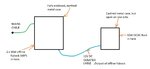
We are doing radiated emissions testing on SMPS’s in metal enclosures with an inter-connecting cable (as attached).
We only have a few hours in the expensive-to-hire emissions lab.

We want to modify snubbers etc on the SMPS’s, then see what effect it has on the radiated emissions. However, we fear the interconnecting cable may change position in between the modifications, and that itself may alter the radiated emissions at the receiving antenna. Do you have thoughts on this?
 

Attachments

  • Radiated emissions.jpg
    Radiated emissions.jpg
    66.9 KB · Views: 85

1) Don't move your cable.
2) If just moving your cable causes you to fail the test, you've got a marginal design. Fix your design.
 
  • Like
Reactions: treez

    T

    Points: 2
    Helpful Answer Positive Rating
1) Don't move your cable.
2) If just moving your cable causes you to fail the test, you've got a marginal design. Fix your design.
Thanks,The cable is not fixed.The product is sold with a cable between them, the cable can come to rest in whatever position. Theres no cable conduit/trunking. That would be too expensive.
Sorry but i cannot see how you say its marginal because moving the cable affects the signal strength detected at the EMC antenna?...after all, the cable is the main causation of radiated emissions...the cable is after all, the noise antenna(?)....so surely the fact that we have a cable which can reside in any position, means we have had it for getting repeatable radiated scans? Are we doomed to never be able to make circuit mods toward getting a radiated emission pass?
 
Last edited by a moderator:

So, you post this same junk in a different forum and note that you are connecting two boxes with high frequency noise and NOT using a shielded cable. No shielded cable, and you don't think that's a marginal design?
 
  • Like
Reactions: treez and d123

    T

    Points: 2
    Helpful Answer Positive Rating
Rather than spamming multiple threads about the same issue, it would be better if you gave sufficient detail to actually understand the problem. In particular, your diagram should show:
1. Any connection between the system and the test chamber's earth ground (I'm guessing the only thing here would be the earth line of the mains cable)
2. Every circuit element which connects to each chassis (either via direct connections or capacitors)
3. Every isolation barrier, and any capacitors spanning them
4. Any relevant filters, common mode or differential

This would clear up a lot of ambiguity. For example, your diagram indicates that the only cable connected to the second enclosure is "isolated", but it also says that the two enclosures it connects to are earthed. How can that be true?
 
  • Like
Reactions: treez

    T

    Points: 2
    Helpful Answer Positive Rating
1. Any connection between the system and the test chamber's earth ground (I'm guessing the only thing here would be the earth line of the mains cable)
2. Every circuit element which connects to each chassis (either via direct connections or capacitors)
3. Every isolation barrier, and any capacitors spanning them
4. Any relevant filters, common mode or differential

This would clear up a lot of ambiguity. For example, your diagram indicates that the only cable connected to the second enclosure is "isolated", but it also says that the two enclosures it connects to are earthed. How can that be true?
Thanks
1....Yes the only earth connection to RHS box is the earth wire in the interconnecting cable.
Only earth connection to LHS bos is from the earth wire in the mains cable.
2...One SMPS in the LHS box is in a safety earthed box, which is screwed to chassis.
3...There are two isolated flyback SMPS's in the LHS box, each has a Y cap across its isolation barrier.
4....There is, as yet, no common mode chokes at the buck. Flybacks in LHS box have input CM chokes.

your diagram indicates that the only cable connected to the second enclosure is "isolated", but it also says that the two enclosures it connects to are earthed. How can that be true?
The interconnecting cable that connects to the RHS box from the LHS box has three conductors (and a foil screen/shield which is connected to the third conductor).......isolated 12V and its return...and also a third wire which is connected to the earthed chassis of the LHS box. (and it is connected to the chassis of the RHS box...which is then earthed via that same connection.
 

Since the system only connects to earth at one point (aside from stray capacitance), it seems unlikely that common mode currents on the 12V cable are an issue. There's a few simple lab experiments you could do to get more insight:
1. Look at each cable with a high frequency current transformer/probe and compare them to each other, and to any emissions data you have.
2. Probe the voltage on each enclosure with a scope probe or spectrum analyzer (just one point of contact, don't connect the measuring instrument's gnd directly to your system). Do the same comparisons.

Do you have any data that suggests that emissions depends on cable placement, or are you just speculating?
 
  • Like
Reactions: treez

    T

    Points: 2
    Helpful Answer Positive Rating
Do you have any data that suggests that emissions depends on cable placement, or are you just speculating?
Thanks, just speculating.
 

How much slack is there in this cable? If it's slack enough to form loops or knots, then it's possible you may see some significant variation.

If I were you, I would create a test fixture which fixes the positions of the two boxes and the cables, and bring the whole thing for testing. Make the fixture resemble a normal use case. If I know that some normal use cases give worse emissions than others, I'll use the worst one. But it's not up to me to exhaustively prove that it's the worse possible configuration.
 
  • Like
Reactions: treez

    T

    Points: 2
    Helpful Answer Positive Rating
Status
Not open for further replies.

Similar threads

Part and Inventory Search

Welcome to EDABoard.com

Sponsor

Back
Top