Continue to Site

Welcome to EDAboard.com

Welcome to our site! EDAboard.com is an international Electronics Discussion Forum focused on EDA software, circuits, schematics, books, theory, papers, asic, pld, 8051, DSP, Network, RF, Analog Design, PCB, Service Manuals... and a whole lot more! To participate you need to register. Registration is free. Click here to register now.

Radar circuit function

Status
Not open for further replies.

johnny_b4e

Newbie level 5
Joined
Nov 22, 2012
Messages
10
Helped
0
Reputation
0
Reaction score
0
Trophy points
1,281
Activity points
1,364
So, I was searching for typical speed radar circuits and came a cross this:
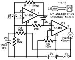
economy-radar-detector_med.jpg

I can't seem to understand how it can detect (measure) level of RF signal.

I guess, C1 with traces to chip forms antenna matched for desired radar frequency, but how can
general purpose amplifier work with GHz range frequency? The output of first amplifier then is fed trough high pass filter
to comparator.

Can anybody explain this?
 

That circuit doesnt work. This is old circuit.

Today laser tech is used for measuring speed of cars. I was kid when police stop to use radars.


Laser Jammer circuit is better topic.
 
Now the vendor use microwave to detect. The principle is doppler freq shift.
I remember some IEEE papers on that, and some Taiwan vendor manufacture that.
The circuit is very simple.
 

That circuit doesnt work. This is old circuit.

Today laser tech is used for measuring speed of cars. I was kid when police stop to use radars.


Laser Jammer circuit is better topic.

Is the problem, the fact that it's old (old design) and new radars use different technology, or the circuit itself is flawed?

Anyway, this was more of an educational question, I'm sure there are more useful examples.
 

Today police use lasers, not radars, but who knows. They need precision in detection, also they need evidence for court, because of that they today include video and photo imaging tech.

I remember this circuit from a few years ago, lots of people try to build that.

- - - Updated - - -

This is circuit decription :

"This circuit uses a 1458 dual op-amp to form a radar detector. C1 is the detector of the radar signal. The first op-amp forms a current-to-voltage converter and the second op-amp buffers the output to drive the piezo transducer. R5 sets the switching threshold of the second op-amp; normally it is adjusted so that the circuit barely triggers on background noise, then it's backed off a bit. The response of the circuit may be tuned by adjusting the length of the leads on C1. For typical road-radar systems, the input capacitor's leads should be about 0.5 to 0.6 inches long."
 

Status
Not open for further replies.

Part and Inventory Search

Welcome to EDABoard.com

Sponsor

Back
Top