Continue to Site

Welcome to EDAboard.com

Welcome to our site! EDAboard.com is an international Electronics Discussion Forum focused on EDA software, circuits, schematics, books, theory, papers, asic, pld, 8051, DSP, Network, RF, Analog Design, PCB, Service Manuals... and a whole lot more! To participate you need to register. Registration is free. Click here to register now.

[SOLVED] Quick circuit question

Status
Not open for further replies.

bowman1710

Full Member level 3
Joined
Nov 8, 2014
Messages
183
Helped
6
Reputation
12
Reaction score
6
Trophy points
18
Activity points
1,604
Hi guys,

Im looking at this circuit of a feedback circuit, what is the purpose of the circuitry highlighted in the attached picture. Also, what is the 100K resistor adding to this?

feedback.PNG
 

my impression is that the 100K is setting the output voltage

The 787ohm and 2.49K are setting the output voltage of the design, with a Vref of 2.5V

and the highlighted circuitry is the output stage.
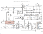
What do you mean by output stage?? I would of said it was more of a current source type of thing.


Full schematic attached

Full schematic.PNG
 

My impression is that the highlighted section is for limiting the rate of rise on the output voltage. When at steady state, it does nothing since the 0.68uF cap blocks all current. But if Vout rises quickly than it will conduct and it will forcibly pull the COMP pin of the controller down, forcing the output current to decrease immediately.

Not sure about the 100K.
 
Hard to tell without the full diagram, but this open collector IC output regulates the opto isolator feedback to maintain equal V+,V-

Vout is ac coupled to a common emitter device with a Shottky diode clamp , so that if there is current spike that exceeds 0.6V/330R it also saturates the collector to turn on the Opto feedback, while the 100K to gnd reduces the turn off time. Since Re is small (47R) and Opto diode pullup is large (1k) it operates as a comparator with high voltage gain for positive spikes only.
 
Thanks Mtweig for your reply i think it is very similar to Sunnyskyguy.

Hard to tell without the full diagram
. I put it in post #3 to help :), it was along the line of what i was thinking initially. I just needed someone with more experience to explain it in more detail to me. This then leads to my next question. Why would you want a high voltage gain when there are current spikes?
 

Hard to tell without the full diagram, but this open collector IC output regulates the opto isolator feedback to maintain equal V+,V-

Vout is ac coupled to a common emitter device with a Shottky diode clamp , so that if there is current spike that exceeds 0.6V/330R it also saturates the collector to turn on the Opto feedback, while the 100K to gnd reduces the turn off time. Since Re is small (47R) and Opto diode pullup is large (1k) it operates as a comparator with high voltage gain for positive spikes only.

My quick review of the full schematic.

It has both primary and secondary regulation. The cct. in question seems to be for fast OVP protection perhaps from a step load being removed.

Since it is AC coupled, it is not a fixed OVP but rather a transient OVP for both a smoother startup and transient load disconnects, causing the startup to only step-up slower by the Vbe limited threshold at some cycle rate and thus reduce inrush current on power up.... and that's my final answer.

Now how much OVP? ~>=0.65V with a dynamic load of the diode or 5.7Ω which would draw 114 mA pulse across the output which in turn momentarily shuts off the primary regulator for at least a few µs.

So it both loads the secondary with >100mA and shuts off the primary regulator momentarily.

BAT54 Specs
VF 240 320 400 500 800 mV
IF = 0.1 1.0 , 10 , 30 100mA
This means BAT54 ESR characteristic above 500mV is 400mV/70mA = 5.7Ω
Thus incremental voltage must reach ~0.65V for Vbe to saturate across 330Ω and diode 500mV+If*5.7Ω to stop the primary regulator momentarily with the RC time constant controlled by diode ESR.

Simple question... not so simple answer.
 
Thanks SunnySkyguy, it has been much appreciated I have now marked this as solved. I didnt think that it was going to be a straight forward one, hence why i couldn't quite get it, a few more years of experience and maybe i will.
 

Status
Not open for further replies.

Part and Inventory Search

Welcome to EDABoard.com

Sponsor

Back
Top