Continue to Site

Welcome to EDAboard.com

Welcome to our site! EDAboard.com is an international Electronics Discussion Forum focused on EDA software, circuits, schematics, books, theory, papers, asic, pld, 8051, DSP, Network, RF, Analog Design, PCB, Service Manuals... and a whole lot more! To participate you need to register. Registration is free. Click here to register now.

[SOLVED] Questions about using npn transistor as a high side switch

Status
Not open for further replies.

skywalker898

Member level 1
Joined
Jan 31, 2012
Messages
32
Helped
0
Reputation
0
Reaction score
0
Trophy points
1,286
Location
Madison, WI
Activity points
1,622
Hi, I would like to use an npn transistor as a high side switch, but I have seen multiple websites stating that a pnp transistor should be used for a high side switch. Could someone tell me if it matters whether the npn transistor is used as a high side switch vs a low side switch? I don't understand why it matters whether the load is on the collector vs the emitter. Please see the simple example I uploaded. npnHighSideSwitch.jpg

Also, in my actual application, I need a high side switch (to switch 90V DC) that I can control with TTL voltage levels. Can I do this with an npn transistor (or multiple)? For example, take my LED switch example, how can I use npn transistors to switch 90V DC using only 5V TTL output from my microprocessor.

Thanks,
Brandon
 

Re: npn high side switch

What you've got in your right-hand drawing is an emitter-follower(load is in the emitter). In order for the NPN to conduct, the base must be Vbe (about 0.7V) higher than the emiitter, so for your case, you would never see more than 4.3 volts at the emitter (assuming 0 base current)
 
Re: npn high side switch

Why do you want to use NPN only?
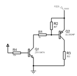
A circuit like the following can control a high side PNP using a low side NPN.
R3 is the load, the resistors and transistors should be changed to match the circuit requirements (voltage and current)

pnp_from_npn2.gif
 
Re: npn high side switch

Thanks alexan_e. Controlling the PNP transistor with a low side NPN is a really good idea. Could you explain how to determine the value of R2 and R1 in your circuit? For example, I will drive the NPN with +5V, R3 will be 1.5k, and I need 20mA through R3. What is the reasoning behind the values for R1 and R2?
 

Re: npn high side switch

R2 works as a pullup resistor to keep the base positive when the NPN is off so that the PNP is off too.
When NPN turns on it sinks current through R1+R2 and this creates a voltage drop to the base of PNP which turns it on.

For 20mA output you need about 1/10 to 1/20 of that as base current so lets say 2mA.
The current in the base of the PNP will be about (12v-0.7v)/1K = 11mA , this will be more than enough to dive a 100mA load (calculated with 12v supply in the emitter of PNP)

There will be a small Vce voltage drop at the NPN but for calculations you can use the power supply voltage (12v in my example).
There will also be a small percentage of the PNP base resistor (R1) current that will escape through R2 instead of going to the base , it can be calculated by 0.7v/R2 (about 0.1mA in this case)
 
Last edited:
Status
Not open for further replies.

Part and Inventory Search

Welcome to EDABoard.com

Sponsor

Back
Top