Continue to Site

Welcome to EDAboard.com

Welcome to our site! EDAboard.com is an international Electronics Discussion Forum focused on EDA software, circuits, schematics, books, theory, papers, asic, pld, 8051, DSP, Network, RF, Analog Design, PCB, Service Manuals... and a whole lot more! To participate you need to register. Registration is free. Click here to register now.

question regarding opamp- ac signal disappears

Status
Not open for further replies.

Akramin84

Newbie level 6
Joined
Feb 24, 2009
Messages
12
Helped
0
Reputation
0
Reaction score
0
Trophy points
1,281
Activity points
1,355
question regarding opamp

i got mixed signal ac and dc, i just want to amplify ac signal so i put coupling capacitor to filter dc. the problem occur ac signal disappear when i connect to the non inverting pin of opamp. anyone can give me solution ????
 

question regarding opamp

wht r u connecting to ur non inverting pin?
 

Re: question regarding opamp

i'm connecting to non inverting pin of the opamp.the volatge is 2.5 V dc and a few hundred mV. I just want to filter the dc part.but im still looking the right value and type of capacitor .whether tantalum ,electrolitic of ceramic...anyone can help me with this.....

Added after 22 seconds:

i'm connecting to non inverting pin of the opamp.the volatge is 2.5 V dc and a few hundred mV ac . I just want to filter the dc part.but im still looking the right value and type of capacitor .whether tantalum ,electrolitic of ceramic...anyone can help me with this.....
 

Re: question regarding opamp

Please attach your circuit.
 

    Akramin84

    Points: 2
    Helpful Answer Positive Rating
Re: question regarding opamp

Akramin84 said:
i got mixed signal ac and dc, i just want to amplify ac signal so i put coupling capacitor to filter dc. the problem occur ac signal disappear when i connect to the non inverting pin of opamp. anyone can give me solution ????

It is a typical error: it is NOT allowed to place a cap directly in front of any opamp input.
The reason: No bias current can flow.
You must connect a large resistor to ground in addition.
 

Re: question regarding opamp

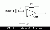
thank you of all your help....i already solve the prob....instead of putting ceramic capacitor to filter dc , i put tantalum 47uf and everything work just fine.however ,i don't really understand the theory behind this dc filtering. how the value of capacitor affect dc voltage ? anyone can provide me with the reference ? .here i attach the circuit diagram..


Re: question regarding opamp

Akramin84 said:
thank you of all your help....i already solve the prob....instead of putting ceramic capacitor to filter dc , i put tantalum 47uf and everything work just fine.however ,i don't really understand the theory behind this dc filtering. how the value of capacitor affect dc voltage ?

There is no dc filtering, as dc is simply blocked. Therefore, the value of the cap has no influence on dc blocking. However, the cap value determines - together with resistor value - the corner frequency for ac performance.
 

Re: question regarding opamp

oooo i see can you give equation regarding this matter ?????
 

Re: question regarding opamp

Akramin84 said:
oooo i see can you give equation regarding this matter ?????

The gain is: \[\frac{V_o}{V_i} = - \frac{R_2*C*s}{1+R_1*C*s}\] where s=j*w and j is the complex unit. So in complex form, you get: \[\frac{V_o}{V_i} = - \frac{R_2*C*j*w}{1+R_1*C*j*w}\]

So ploting the gain versus frecuency, you get something like this:

Bode_High-Pass.PNG

(This is just a descriptive image, the values are for another system or R and C values)

The label 'Frecuency' in the graph, is w = 2*pi*f, so, if you want the frecuency in Hz, you must calculate: \[f = \frac{w}{2*pi}\]

The frecuency w=100 in this graph, corresponds to the pole at \[w = \frac{1}{R_1*C}\] of your system, and the gain at high frecuencies is \[\frac{V_o}{V_i} = -\frac{R_2}{R_1}\], not 0 like in the graphic.

In a simple manner, the capacitor is a open circuit at low frecuencies, and a shorted circuit at high frecuencies.

Everything i wrote is true, only if you consider the operational amplifier completly ideal.
Regards, Diego.

By the way, "in the real world", if you want to reduce the DC level at the output, you must connect a resistor between the non inverting input of the Operational Amplifier, and ground, instead of connecting it directly to ground.
The value must be \[R_1||R_2 = \frac{R_1*R_2}{R_1+R_2}\].
 

Status
Not open for further replies.

Similar threads

Part and Inventory Search

Welcome to EDABoard.com

Sponsor

Back
Top