Continue to Site

Welcome to EDAboard.com

Welcome to our site! EDAboard.com is an international Electronics Discussion Forum focused on EDA software, circuits, schematics, books, theory, papers, asic, pld, 8051, DSP, Network, RF, Analog Design, PCB, Service Manuals... and a whole lot more! To participate you need to register. Registration is free. Click here to register now.

Question of an absolute value circuit

Status
Not open for further replies.

bhl777

Full Member level 6
Joined
Sep 30, 2008
Messages
363
Helped
0
Reputation
0
Reaction score
0
Trophy points
1,296
Activity points
5,140
Hi All, I am reading one application notes from https://www.analog.com/library/analogDialogue/archives/44-04/absolute.pdf.

They use two op amps to realize absolute value circuit without using diode. But I have a question of its operating. Could someone give me some explanation of it?

Like this circuit
absolutevalue1.PNG
As the author decribed, when A pint has a negative input(for example, -5V), B point will be around 0V. Then A2 will be used to invert this negative voltage to positive.

I do not understand why when A node has a negative input, B node will be 0. It seems like A1 op amp does not work in this circumstances.

Could anyone advise? Thank you!
 

I suspect the first opamp is running off a single supply; thus as the input goes negative, the output is forced to ground.
 

Hi Barry, yes both opamp are in a single supply. I did some simulation and it showed that in steady state Vin+ of first opamp will be kept at -5V while Vin- is kept at 0V (the same as Vout of first opamp).
Could you tell me more about "output forced to GND"?

I suspect the first opamp is running off a single supply; thus as the input goes negative, the output is forced to ground.
 

First of all, that's a pretty goofy schematic. Why are there parallel resistors? Why is there a resistor in the feedback path of the 1st opamp-it's just a voltage follower-resistor not really needed.

Anyway, when the input to the first opamp (gain of 1) goes negative, the output 'wants' to go negative but can't; it can only go as low as ground, right?
 
  • Like
Reactions: bhl777

    bhl777

    Points: 2
    Helpful Answer Positive Rating
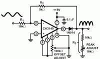
The application circuit in the original post can be better understood by looking at the AD8277 datasheet, I think. It's one of those far-fetched design ideas that can be only found in manufacturer's suggestions. If we talk about simple full wave rectifier circuits, I would rather think of a classical example from CA3140 datasheet. Of course you can design many other circuits utilizing single supply saturation instead of diodes. But are they better than a standard two-OP full-wave rectifier from analog design textbooks?


Interesting parameters of full-wave rectifiers (or "absolute value" circuits) are dynamic range versus operation frequency and offset errors. Without referring to specific parameters in this regard, advantages and drawbacks of different topologies, the discussion isn't really motivating for me.
 
Status
Not open for further replies.

Part and Inventory Search

Welcome to EDABoard.com

Sponsor

Back
Top