Continue to Site

Welcome to EDAboard.com

Welcome to our site! EDAboard.com is an international Electronics Discussion Forum focused on EDA software, circuits, schematics, books, theory, papers, asic, pld, 8051, DSP, Network, RF, Analog Design, PCB, Service Manuals... and a whole lot more! To participate you need to register. Registration is free. Click here to register now.

question in dealing with LPT IO pins

Status
Not open for further replies.

asrock

Junior Member level 3
Joined
Sep 10, 2010
Messages
26
Helped
0
Reputation
0
Reaction score
0
Trophy points
1,281
Activity points
1,538
hello every one


i have a question about reading lpt data that PIC control them ,
& i made a software to read from lpt ,,, but the issue in connecting PIC with lpt !


i mean >>> can i connect LPT pins directly to PIC pins (such as PORTA) ?!!

or are there any equipments that i must connect before ?

i use PIC16f877 & MikroC ,,,

so any one here can help me with any schematic plz

gratings :)
 

Maybe this thread will give you some help to find out: https://www.edaboard.com/threads/273541/

Enjoy your design work!


thanks a lot mr.HTA for ur link

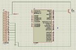
here i draw a schematic how to change the pin1 of lpt as PIC rb0 ,,

when i trigger bc337 , the state of pin1 is "1" , else state is "0"

So is this schematic right?? ,, i don't test it in fact ,but i would know if it is right ,,

what's is your opinion ?
lpt.jpg
 

Hi Asrock,

Pin 2 of the printer port is an output and if you want to generate an interrupt signal on PIC rbo it need to drive the base of the transistor via a resistor to limit the current. The collector should e connected via a resistor to 5V and drive the PIC rb0 input.

Enjoy your design work!
 

Status
Not open for further replies.

Similar threads

Part and Inventory Search

Welcome to EDABoard.com

Sponsor

Back
Top