Continue to Site

Welcome to EDAboard.com

Welcome to our site! EDAboard.com is an international Electronics Discussion Forum focused on EDA software, circuits, schematics, books, theory, papers, asic, pld, 8051, DSP, Network, RF, Analog Design, PCB, Service Manuals... and a whole lot more! To participate you need to register. Registration is free. Click here to register now.

[SOLVED] Question about potentiometer in audio circuit

Status
Not open for further replies.

obrien135

Full Member level 5
Joined
Nov 10, 2009
Messages
240
Helped
5
Reputation
10
Reaction score
5
Trophy points
1,298
Location
Connecticut
Activity points
3,259
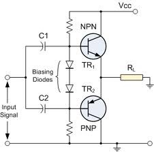
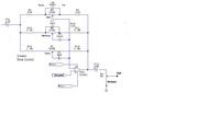
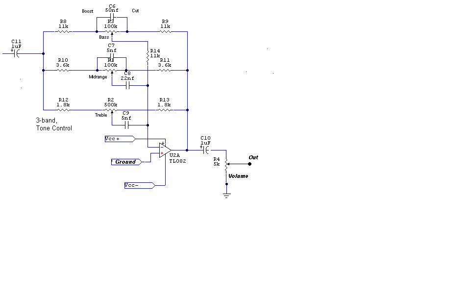
When I turn up the volume on one of the channnel of an audio circuit that I devised. It doesn't give any sound untill the pot is about half way turned up. Then it is distorted. It is preceeded by a tone control circuit using op amps. The power output is a push pull arrangement. I checked the linearity of the pot and it seems OK. All the biasing before and after it is good. I don't have a scope available right now. What do you think might be the problem?

96_1294780348.jpg


All the biasing before and after it is good.
I don't believe that it actually is. But you can watch the AC levels along the signal chain with a sensitive multimeter, if you don't have an oscilloscope. Try to determine, where the signal gets lost below the said threshold. Also the bias is possibly changing versus level control. I guess, it's not a defective (scratching voice coil) speaker?
 
Your two series diodes probably have less voltage drop then the two output devices Vbe's so transistors are is full cutoff. Try putting a resistor in series with the two diodes and adjust until you get a reasonable idle bias in output devices.

This circuit has a voltage gain close to 1. Bias current depends on required load current divided by transistor current gain.
 
One of the great advantages of looking for a fault in just one channel of a 2-channel system is that you still have a working channel which you can use for testing!

I suggest that you cut the circuit where each stage joins to the next; this could be a) at the beginning of the tone circuit, b) the end of the tone circuit, c) at the start of the power amplifier, d) the connections to the speakers.
You can then take a wire from a) on the working channel to a) on the faulty channel and another wire from a) on the faulty channel to a) ont he working channel.
You can now listen for the fault in both channels. When you hear it, this will tell you if the fault is before or after a).
You can repeat this for b), c) and d) until you know which small part of the circuit is causing the problem.

This is quite a common fault in audio circuits, but caused by several things such as a leaky capacitor (or capacitor the wrong way round) or an OpAmp which has too much DC bias on it (or has an internal bias fault) or a power amp with wrong crossover bias current, and some other causes.

One small thing in your power amplifier circuit isn't quite correct. C2 is shown the wrong way round, but I don't expect it would be enough of a problem to explain the fault.
 
The circuit, as shown will actually work as a class A amplifier, because the load is connected to the negative supply. But I guess, the schematic is incorrect. You didn't tell, if there are any circuits between the level pot and the shown output stage, and what is exactly connected to the output.
 
But you can watch the AC levels along the signal chain with a sensitive multimeter, if you don't have an oscilloscope.

My meter only goes down to 200VAC. I itried it anyway but couldn't see a noticable difference going into the push pull circuit. I might have access to a scope later in the week, after the storm.

---------- Post added at 23:02 ---------- Previous post was at 22:56 ----------

Yes, this could be the problem. Before I try it, I would like to take into consideration that the other channel is biased the same way, and works fine. Also I actually tried lowering the series resistance this morning by putting a 10kohm resister in parrallel with both ends. The original one was 7Kohms. This didn't help. I took the forward on voltage of the transisters into consideration when I chose the original value.

---------- Post added at 23:04 ---------- Previous post was at 23:02 ----------

Yes, thank you, I might try that after I look at it with the scope. Thank you for your input.

---------- Post added at 23:06 ---------- Previous post was at 23:04 ----------

There is no circuit between the tone control circuit and the push pull circuit. The push pull output is capacitively coupled to a 4 ohm speaker on it's output.
 

You should also determine the transistor bias currents (there should be some with a reasonable class AB-circuit). Possibly one output transistor is defective or not connected correctly. You would only see it by looking at the voltage differences exactly.
 
Perhaps one of the transistors is defective. They got hot when I had a short when I first powered it up. They both check out good with the diode checker, but maybe they're not working quite right, or just one of them. Is that possible? The biasing voltages are exactly the same on both channels, and so are all the dc voltages throughout the push pull section (one channel in comparison with the other, that is). Could it still be a bad transistor?
 
Last edited:

Without checking the transistor bias currents, it's hard to determine.

Another way to check the output stage operation is to inject a current into the output node and watch how the voltages change. This way you can determine the linearity and the current gain without an oscilloscope. A current can be injected by connecting a variable resistor in parallel to one of the output transistors.
 
I figured out the problem. I did as DXNewCastle suggested and isolated different stages and swapped them to isolate the circuit that had the problem. It ended up being the output section. I looked at the biasing voltages again, and although I originally thought they were all right, it turns out there was a miswire and the base of the TIP31 was connected to the cathode of the 1n4148 instead of the anode. My soldering iron is in a different town, but I corrected the problem in a makeshift way using alligator clips and cutting wires. After that it worked great, with no distortion. When I get ahold of the soldering iron I will make the changes permanent. Thanks for helping me solve the problem, fellows.
 

Status
Not open for further replies.

Similar threads

Part and Inventory Search

Welcome to EDABoard.com

Sponsor

Back
Top