Continue to Site

Welcome to EDAboard.com

Welcome to our site! EDAboard.com is an international Electronics Discussion Forum focused on EDA software, circuits, schematics, books, theory, papers, asic, pld, 8051, DSP, Network, RF, Analog Design, PCB, Service Manuals... and a whole lot more! To participate you need to register. Registration is free. Click here to register now.

question about a circuit ( multiplier )

Status
Not open for further replies.

Zara Zara

Junior Member level 1
Joined
Apr 6, 2015
Messages
15
Helped
0
Reputation
0
Reaction score
0
Trophy points
1
Activity points
104
Hello

I found this circuit in an old book , I've drawn the circuit ( attachement) .

With :
- F : clock signal 100 Hz
- M is a DC signal from -5 to +5

The author said that the result is M*F.

Please let me know

thanks in advance
Zara
 

Attachments

  • Multiplier.JPG
    Multiplier.JPG
    30 KB · Views: 77

I guess you omitted an important detail. There should be an analog switch connected to node F. The circuit is operating as a sign multiplier then.
 

Hello

I guess you omitted an important detail. There should be an analog switch connected to node F. The circuit is operating as a sign multiplier then.

Sorry FvM, but i didn't understand what's the importance of an analog switch if F does the job in the circuit by switching between -1 and +1 per example.

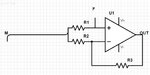
Please can you help me to conclude a equation of Vout in function of Vin to understand more.

thanks FvM
 

If you are asking about a specific circuit, you should show it completely. The circuit shown in post #1 is a linear OP circuit that can't work as a multiplier.

In case you mean a +/- 1 switchable gain ("sign multiplier") circuit, see this previous thread.
https://www.edaboard.com/threads/289173/
 

Hello FvM

Thanks for your help , i understand the idea now.

Zara
 

Status
Not open for further replies.

Similar threads

Part and Inventory Search

Welcome to EDABoard.com

Sponsor

Back
Top