rfm
Newbie level 3
Hello,
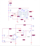
I have been tinkering with the constant current sources recently and want to drive my 30 W LED using it, I have simulated the circuit below and it seems to give me the correct current.
Basically the current source (1A) is created using the OPAMP circuit, but I also want to pulse the output using the 555 timer, can I please request that somebody look at the attached circuit and advise whether I would have any issues with it before I build it.
I am mostly worried about the pulsing part using the 555 timer where the voltage level is different (1.8V) and I have coupled it to the opamp output (32V) using a 10uF capacitor. Any help and guidance will be much appreciated.
