Continue to Site

Welcome to EDAboard.com

Welcome to our site! EDAboard.com is an international Electronics Discussion Forum focused on EDA software, circuits, schematics, books, theory, papers, asic, pld, 8051, DSP, Network, RF, Analog Design, PCB, Service Manuals... and a whole lot more! To participate you need to register. Registration is free. Click here to register now.

PWM generation using TL494

Status
Not open for further replies.

abe94

Member level 1
Joined
Jun 20, 2015
Messages
34
Helped
0
Reputation
0
Reaction score
0
Trophy points
6
Activity points
378
I need to generate a fixed frequency and variable duty cycle PWM signal. Normally I would've used a microcontroller , but due to unavoidable circumstances , I have to use the TL494. I did an extensive study of the datasheet , but there are some doubts which need to be cleared. The picture shows the block diagram of the TL494.

Screenshot - 09132015 - 02:16:41 PM.png

What I've decided to do is to connect the Vref pin to the FEEDBACK pin. According to the datasheet , the Vref pin is a reference voltage source of 5V. I'll put a pot in between the Vref pin and the FEEDBACK pin. That way I can control the voltage input into the FEEDBACK pin from 0 - 5V. If my understanding of PWM generation is correct , the PWM comparator should do its work by comparing the DC signal from feedback and the sawtooth from the oscillator. I have 5 questions.

1. Am I doing this right ? I know the TL494n is supposed to be used as a closed loop system with the feedback coming from the output section of the power supply. I want to re-purpose it as a PWM generator with duty cycle controlled by a pot.

2. What confuses me is what am I supposed to do with the other pins , like the error amplifiers and the DTC . Should I leave them unconnected ? Should I pull them to ground ?

3. I'm using the Vref pin as a voltage source. Is this good practice ? Or should I use a separate 5V source ?


4. I want to get single-ended output from the chip , not push pull. This is kind of a newbie question , but how do I wire up the pins for this mode ?

5. I think instead of FEEDBACK pin , I should use the error amplifiers to provide the control signal to the PWM comparator. Would my original method be alright ? If no , then how can I do that ?


Datasheet : https://www.ti.com/lit/ds/symlink/tl494.pdf

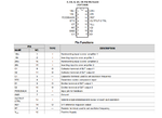
Pin Diagram :
Screenshot - 09132015 - 02:34:35 PM.png
 

You can drive the feedback directly with the control voltage, but it will be loaded with up to 0.7 mA pull-down current. Or use one of the error amplifiers as buffer. Unused error amplifiers should be biased for low output voltage.

To get full duty cycle range for a single output, both output transistors are connected parallel.

DTC sets the maximum duty cycle.
 

Hi,

To generate a fixed frequency, variable duty cycle PWM, you just need a dual comparator, a couple of Cs and Rs.

With one comparator(totem pole output),four resistors and a C you generate the frequency. The feedback signal is about a triangle waveform.
Three equal resistors, about 10k, all three in a star. Star point to In+. One R to GND, one to VCC and one to the comparator output.
One RC as frequency setup. R from comparator output to In-, the C to GND.

The triangle RC signal is also one input for the second comparator.
The other input signal is the duty cycle control input. The input voltage range is 1/3 Vcc to 2/3 Vcc.

Klaus
 

. Or use one of the error amplifiers as buffer. Unused error amplifiers should be biased for low output voltage.
So I should use one error amp as an input buffet and bias the other error amp to have zero o/p voltage from it ? Okay good. But how do I do that ? For the buffer would connect the FEEDBACK pin to the inverting
Pin and the control voltage to the noon inverting pin. How do I bias the other error amp to get zero o/0 voltage ? Should I ground both pins ? That way the difference in the inputs would be zero and the output of the amp would be zero.
To get full duty cycle range for a single output, both output transistors are connected parallel.


DTC sets the maximum duty cycle.
So the error amps are used for varying the duty cycle and the DTC is used for selecting the max duty cycle ? In my case , it should be pulled to ground to ensure max duty cycle. Am I right ? I'm looking to vary the duty cycle from 0 to 90-80 %.

Thanks for your help ! I'm already getting the hang of things.
 

Everything correct, except for

Should I ground both pins ? That way the difference in the inputs would be zero and the output of the amp would be zero.

Error amplifier output with both inputs zero is undefined, could be high or low. Bias the input with Vref, as shown in the test circuit.
 

Alright. Thanks. What about the DTC pin ?
 

I agreed also about DTC. Grounding it gives about 90% maxim duty cycle.
 

Thanks for the help ! I'll post a schematic soon. I'm actually using the PWM to control a triac. The whole system is an AC Chopper.
Using 20khz frequency for the PWM.
 

You can't operate a triac at 20 kHz because the turn-off time is in a 100 µs range. The other question is if your circuit allows triac self turn-off.
 

For fixed frequency and variable duty cycle PWM signal, you can try this single-chip **broken link removed**.
 

Okaay. So what do I do now ? I got the idea from a textbook. Do I change the switching device ? Or do I reduce the pwm frequency ?

- - - Updated - - -

You can't operate a triac at 20 kHz because the turn-off time is in a 100 µs range. The other question is if your circuit allows triac self turn-off.

20khz was me pulling a number out of thin air. I was actually going to decide the pwm frequency next. If the triac turn off time is 100us then the max frequency I can use is 10khz . Is this right ? The TL494 datasheet suggests the recommended minimum oscillator frequency is 1 khz. So I've got the choice from 1 - 10khz. Any method of selecting the optimal PWM frequency ? What about self turn off ? The circuit is like a usual full bridge AC voltage controller using two thyristors or one triac. I'm isolating the control circuitry from the switch by using a MOC3041 optoisolator. The schematic I'm using to connect the triac is the one shown in the MOC3041 datasheet. What other factors should I check ? Can you give me some pointers about how to approach this ?


Thanks again FvM. You've helped me in my previous posts on edaboard too. Your help is invaluable.
 

What about self turn off ? The circuit is like a usual full bridge AC voltage controller using two thyristors or one triac.

The circuit can only turn off, if the triac current crosses zero. Don't think that it will work as chopper for you.
 

The circuit can only turn off, if the triac current crosses zero. Don't think that it will work as chopper for you.
The MOC3041 has a zero cross detector in it. Triggers the triac after the zero crossing of the sinusoidal wave. Maybe that's supposed to do something ? If it didn't work then why would they put it in a textbook ?
 

I'm not talking about zero-crossing detector trigger.

A triac or thyristor is a latching switch element. It can't switch of the current after it has been triggered. You have to wait until the external circuit stops the current. For this reason, it's not possible to generate PWM with a triac or thyristor at a higher frequency than that of the AC voltage supply.
 

For this reason, it's not possible to generate PWM with a triac or thyristor at a higher frequency than that of the AC voltage supply.
Okay so my pwm has to have a frequency equal to or below 50Hz. Well then it seems my approach has been totally wrong. I'll have to generate the pwm using separate oscillator and comparator stages fine tuned for this.

- - - Updated - - -

A triac or thyristor is a latching switch element. It can't switch of the current after it has been triggered. You have to wait until the external circuit stops the current.

Would any other power switch work for this application so that I don't have to change the pwm generation circuitry ?
 

Status
Not open for further replies.

Similar threads

Part and Inventory Search

Welcome to EDABoard.com

Sponsor

Back
Top