Continue to Site

Welcome to EDAboard.com

Welcome to our site! EDAboard.com is an international Electronics Discussion Forum focused on EDA software, circuits, schematics, books, theory, papers, asic, pld, 8051, DSP, Network, RF, Analog Design, PCB, Service Manuals... and a whole lot more! To participate you need to register. Registration is free. Click here to register now.

[SOLVED] PWM applied to load while current limiting on load simultaneously

Status
Not open for further replies.

farzadlatifeh

Newbie level 6
Joined
Dec 1, 2019
Messages
13
Helped
1
Reputation
2
Reaction score
1
Trophy points
3
Activity points
127
Hey there
I have an electrolysis cell to produce brown's gas from water, in the process, gas barrier decreases efficiency of cell while it may consume huge amounts of current too.
So, I need to apply PWM pulses to increase electrode efficiencies and control current consumption in one circuit.

I have this current limiter example
IFD2634_F2-big.gif

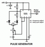
And this simple PWM generator
pulse-generator.gif

But I have no clue how to couple them in one circuit for load full control, I mean can I just use one FET in series with load that PWM circuit controls it? Is that so simple though? Or I should do some modifications to reach the target!
If anyone here can help me, I'll be really appreciated.
 

Q1 in your current limit circuit is always switched off I think, doesn't look good.
Why don't you look for an IC? Basically you need a DCDC converter with adjustable output voltage and current limit. I am sure you can find one which can provide your needs.
 
Q1 in your current limit circuit is always switched off I think.
No. The photovoltaic opto coupler VOM1271 is generating a positive gate sourve voltage. It's a slightly extravagant way to build a NMOSFET linear regulator.

Combining the circuit with PWM might be difficult due to the relative slow VOM1271 operation. It might be easier to switch to a different gate drive method.

More generally, I doubt that PWM can increase water electrolysis efficiency. Any references?

Powering an electrolysis cell by a linear current regulator will involve huge losses in any case. A switched mode regulator with storage inductor can achieve a low loss conversion between input voltage and cell voltage.
 
Hi,

I'd replace the LT1636 circuit with a more simple deicated "current sense amplifier". It usually requires just a shunt and a power supply decoupling capacitor..

You try linear regulation (which just wastes power) ... but later you talk about efficiency.
This does not match in my eyes.

Why not using a buck converter with curent limit? It will be way more efficient.

The VOM1271 circuit is rather slow ... either you need a more slow regulation loop, or you should expect instability = oscillation.

Klaus
 
what do mean of adjustable voltage? is that PWM you mean?

……………….

No. The photovoltaic opto coupler VOM1271 is generating a positive gate sourve voltage. It's a slightly extravagant way to build a NMOSFET linear regulator.

Combining the circuit with PWM might be difficult due to the relative slow VOM1271 operation. It might be easier to switch to a different gate drive method.

More generally, I doubt that PWM can increase water electrolysis efficiency. Any references?

Powering an electrolysis cell by a linear current regulator will involve huge losses in any case. A switched mode regulator with storage inductor can achieve a low loss conversion between input voltage and cell voltage.

actually the current limiter is just an example and it is not intended for my device, I'll be really appreciated you if you can find me another one

the reference for PWM electrolysis:
Shaaban, Aly H. (1993). "Water Electrolysis and Pulsed Direct Current". Journal of the Electrochemical Society. 140 (10): 2863. doi:10.1149/1.2220923.

………………..
Hi,

I'd replace the LT1636 circuit with a more simple deicated "current sense amplifier". It usually requires just a shunt and a power supply decoupling capacitor..

You try linear regulation (which just wastes power) ... but later you talk about efficiency.
This does not match in my eyes.

Why not using a buck converter with curent limit? It will be way more efficient.

The VOM1271 circuit is rather slow ... either you need a more slow regulation loop, or you should expect instability = oscillation.

Klaus

actually I don't want to change the Voltage, it is 12V constant, i just want to control the load current consumption and apply PWM to load in both Frequency and duty cycle control
if you have any suggested circuit I would be really thankful

https://en.wikipedia.org/wiki/Pulse_electrolysis#cite_note-:0-4
 

the reference for PWM electrolysis:
Shaaban, Aly H. (1993). "Water Electrolysis and Pulsed Direct Current". Journal of the Electrochemical Society. 140 (10): 2863. doi:10.1149/1.2220923.
The abstract already states (as expectable)
For the range of tested parameters, the results demonstrated that the nonpulsed dc operation required the least electrical power.
 

Hi,

actually I don't want to change the Voltage
But (as far I can see) this is exactly what your "current limiter" in the first circuit does. It reduces voltage (linear) until the current is in the desired range.
This is called "linear" regulation and is the opposite to "duty cycle" regulations.

If you combine both circuits of post#2, then you combine two opposite strategies. This will cause troubles.
I don´t rtecommend this. So, please decide which one you want to choose.

****
Now, as FvM states "DC operation is the most efficient"...
This again leads to my recommednation of post#4: Buck converter with current control.

Klaus
 

Hi,

But (as far I can see) this is exactly what your "current limiter" in the first circuit does. It reduces voltage (linear) until the current is in the desired range.
This is called "linear" regulation and is the opposite to "duty cycle" regulations.

If you combine both circuits of post#2, then you combine two opposite strategies. This will cause troubles.
I don´t rtecommend this. So, please decide which one you want to choose.

****
Now, as FvM states "DC operation is the most efficient"...
This again leads to my recommednation of post#4: Buck converter with current control.

Klaus

So you mean using dc-dc buck converter with current control can both control the current and make pwm?
I can buy one so
 

In my idea, using pwm and controlling duty cycle actually can control the current too? Am I correct?
Can anybody confirm it?
If yes, then I don't need the current limiter anyway!
 

Hi,

I can confirm:
With PWM you may vary duty cycle --> this varies average voltage --> this varies average current.
So you, with PWM you may adjust/regulate current. Average current. This is pulsed current, not straight DC current.

And again, again, as FvM states: "DC" is the most effective. Not Pulsed current --> not PWM.

Thus - if you want high efficiency - you should not use PWM.

If you want high efficiency, then (again) use a buck converter with current control.
* "Current contol" means you may adjust/regulate for the desired current
* while the ouput is (high efficient) DC voltage. The ouput is not PWM´d.
(For sure within the buck converter there will be PWM, but your load will never see and never know this. ... and even you may forget about his "inside PWM". See the buck converter as a "DC in - DC out" device.)

Klaus

OK, thanks, I'll try it for sure to see what happens despite the fact that literature has claimed PWM will produce more gas than DC
Let's see which is the best
 

Which literature particularly? The paper you have linked contradicts.

I know that some conflicts has been reported against the claim of using PWM for electrolysis but some other reports still insisting on the claim as you can see below:
1- Mazloomi, Kaveh; Sulaiman, Nasri B.; Moayedi, Hossein (April 2012). "An Investigation into the Electrical Impedance of Water Electrolysis Cells – With a View to Saving Energy" (PDF). International Journal of Electrochemical Science. 7: 3466–3481 – via ESG.
2- Sorensen, Bent (2004). Renewable Energy. its Physics, Engineering, use, Environmental Impacts, Economy and Planning Aspects. 2004: Elsevier Academic Press. ISBN 0-12-656153-2.
3- Saitta, A. Marco; Saija, Franz; Giaquinta, Paolo V. (2012-05-15). "Ab Initio Molecular Dynamics Study of Dissociation of Water under an Electric Field". Physical Review Letters. 108 (20): 207801. arXiv:1204.1120. Bibcode:2012PhRvL.108t7801S. doi:10.1103/PhysRevLett.108.207801. ISSN 0031-9007. PMID 23003187.

actually in my belief using PWM is still under research but using it under some circumstances and specific conditions specially the Frequency (150 kHz up to 300 kHz) can help to increase the efficiency in total (both from literatures proving and conflicting), and the theory is based on decreasing the double layer in the electrode surface which causes capacitance charge which makes a barrier to transfer charge and ions.

anyway, I searched for buck and boost converters, interesting that some of them work in the range I need, like 150kHz!!! so why bother to design one, but the question here arises, can I use boost instead of buck too???
higher voltage, higher gas production, but may higher current consumption!
I am going to test them, wish me luck though.

If you know, that from fix DC 12V the current consumption is already too high why would you apply higher voltage?
BUCK and BOOST generate DC voltage with relatively small AC ripple, it is not pulsed voltage, so basically doesn't matter clock frequency.
 
If you know, that from fix DC 12V the current consumption is already too high why would you apply higher voltage?
yes sure, I meant to produce more gas, but not in the cost of car battery failure for sure. already I have bought a buck with 8 Amps continuous current capability and voltage and current control, I am going to test it.
BUCK and BOOST generate DC voltage with relatively small AC ripple, it is not pulsed voltage, so basically doesn't matter clock frequency.
it is because these sort of DC-DC converters are intended to use in DC applications and are not suitable for what I want, therefore, some capacitors and maybe inductors are set in the output path to control the pulse and ripples, first I will try the buck and if it was not satisfied enough then I have to modify it, maybe by removing caps and or inductors it will send pulses as I want!
 

Hi,

I don´t see how "car battery failure" comes into play now...

If possible, try to fix one problem first, then the next.


Klaus
 

The standard potential of a water electrolysis cell is 1.23V, applying a higher voltage doesn't increase the gas yield per ampere second but causes losses. Practical electrolysis processes operate at 70 - 80% energetic efficiency, the fuel value of the produced HHO gas is lower than the applied electrical energy.

See https://en.wikipedia.org/wiki/Electrolysis_of_water

As far as I know you're half right
V =R×I
more V in constant R results in more I, so more electron and so more production.
According to following reference "Electrolysis of water will begin around a minimum of 1.2 volts and will increase in rate as the voltage is increased"

**broken link removed**

So you are partially right.
 

So you are partially right.
I'd say, you have partly understood my points. Apparently not yet the point about energetic efficiency.

- - - Updated - - -

To give a simplified example. Assume you get 80% efficiency at 1.5 V cell voltage. Double the voltage and get e.g doubled current and double gas yield. Efficiency however drops to 40%. Because you apply fourfold input power but get only doubled gas production.
 
Status
Not open for further replies.

Similar threads

Part and Inventory Search

Welcome to EDABoard.com

Sponsor

Back
Top