Continue to Site

Welcome to EDAboard.com

Welcome to our site! EDAboard.com is an international Electronics Discussion Forum focused on EDA software, circuits, schematics, books, theory, papers, asic, pld, 8051, DSP, Network, RF, Analog Design, PCB, Service Manuals... and a whole lot more! To participate you need to register. Registration is free. Click here to register now.

PWM and Opto-coupler waveform problem

Status
Not open for further replies.

An_RF_Newbie

Member level 3
Joined
Sep 1, 2020
Messages
64
Helped
0
Reputation
0
Reaction score
0
Trophy points
6
Activity points
507
Hello,

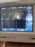
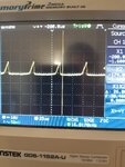
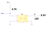
Here is Opt-coupler circuit isolation between my MCU and a motor driver (Attachments). My optocoupler IC is TLP521. As you can see the shape of my output voltage changed based on the input frequency (4 kHz to 16 kHz) where the shape of my output waveform is not acceptable. Based on my concentration, because of the Falling/Rising/Storage time, this problem has appeared in my circuit. As I see, all the optocouplers have the same parameters as my TLP521. Optocircuot voltage is 24V(VCC=24).

  • I need to know how to isolate my circuit and how to get a good waveform up to 50Khz.
  • What is the best optocoupler for my circuit?
 

Attachments

  • 20200901_093632.jpg
    20200901_093632.jpg
    1.8 MB · Views: 134
  • 20200901_093702.jpg
    20200901_093702.jpg
    2.1 MB · Views: 121
  • index.png
    index.png
    5.2 KB · Views: 152

Hi,

Your circuit misses some informations
* The input voltage is shown as 3V3 DC, but it is a PWM. You need to show the drive circuit, too, as well as a scope picture, best as two channel picture. We need to be able to determine LED current and waveform.
* The output is shown as simple pull up resistor. Wiring, additional components, even the scope probe will cause stray capacitance slowing down rise time. We need to see all the output circuit.

But the shown behaviour is quite expectable.

To the datasheet:
It says: Not recommended for new designs
Look at "Switching Characteristics"
Your drive current may be higher than 16mA, thus you get a higher storage time, making the system slow.
Your pullup resistor is higher than 1.9kOhms, thus the rise time in% will be slower.

To speed up optocouplers you need:
* low drive current
* eventually a circuit that "discharges" the input to speed up switch OFF time. (Resistor in parallel to the LED)
* low pull up resistor value
The result is (bad news) low output voltage. The signal is fast, but maybe it just drives 24V (OFF) down to 23.9V (ON).
(And besides this you may risk SOA problems)
To solve this problem:
You need an amplifier at the output side: BJT, Mosfet, comparator...

Or you choose an optocoupler with better performance, they usually are more expensive because they have the amplifier built in.

Klaus
 
Hi,

have a look in the datasheet regarding the switching characteristics. It states a typical turn-off time of 25 µs. For an applied frequency of 16 kHz you are trying to turn on and off the coupler for 31.25 µs, respectively (\[{t}_{ON}\] = \[{t}_{OFF}\] = \[\frac{1}{f }\] \[\cdot\] 0.5). So turning the transistor off lasts for about 56.25 µs, which is almost equal to your switching period time of 62.5 µs.

BR
 
Use distributor search tool and look for optocouplers with logic output and > 1 MHz data rate. There are classical fast opto couplers like 6N137 and many new types.
 
Hi,

I like the logic output optocouplers... but if you want to switch 24V then you need some kind of amplifier.
For logic output optocouplers maybe a logic level MOSFET is useful.
So you may switch up to several 100 Volts and/or several 10 Amperes.

Klaus
 
Status
Not open for further replies.

Similar threads

Part and Inventory Search

Welcome to EDABoard.com

Sponsor

Back
Top