Continue to Site

Welcome to EDAboard.com

Welcome to our site! EDAboard.com is an international Electronics Discussion Forum focused on EDA software, circuits, schematics, books, theory, papers, asic, pld, 8051, DSP, Network, RF, Analog Design, PCB, Service Manuals... and a whole lot more! To participate you need to register. Registration is free. Click here to register now.

Push-Pull SMPS With EI50 Ferrite Core

Status
Not open for further replies.

mcmsat13

Member level 5
Joined
Apr 24, 2013
Messages
94
Helped
4
Reputation
8
Reaction score
4
Trophy points
1,288
Activity points
2,287
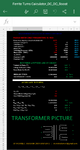
I am building DC DC boost stage for 340VDC, I want to know If I am right about the winding of the EI50 Ferrite transformer because I am no expert to magnetic components.

* Topology = Push-Pull

* VIn(min) = 10.5V

* Vin(nom) = 12V

* Vin(max) = 15V

*Vout = 340VDC

* Vaux = 25VDC

* Output Diode Vf = 0.5V

* Core = EI50

* Core Ae = 2.3cm2

* SW Frequency = 50KHz

* Max Duty Cycle = 94%

Please I need to know the Primary turns
Secondary turns
Auxiliary turns

Thanks in advance.
 

Bpk = E / 4 F N Ae, ( square wave ) for 50kHz, a conservative Bpk = 150mT peak each way, the core area = 230 mm^2

Thus for 340V out Ns = 50 turns, except the duty cycle must be taken into account so divide by 0.94 = 54 turns

10.5V is Vin min - so to get 340V ave out @ 94% applied square wave, Np/Ns = 10.5/340, giving Np = 1.66 Turns

Obviously we round this up to 2.00 turns ( + 2.00 turns for the other ) for the pri, giving 69T for the sec

[ check 10.5V * 69/2 = 362, * 0.94 = 340.5, maybe add a wee bit for the diodes and the wiring loss in the Tx ]

The aux is therefore 25/10.5 * 2T / 0.94 = 5 Turns
 
Last edited:

    mcmsat13

    Points: 2
    Helpful Answer Positive Rating
I would only note that push-pulls have the
potential to "flux walk" with any volt-second
imbalance between the two legs (or winding
asymmetry) and you might need either extra
conservatism or a scheme that ensures
flux balance can't get out of hand. Some
controllers take a stab at that, I gather. If
the imbalance is too much then even being
conservative about the core vs expected
flux won't stop you from eventually saturating
on one phase. And "eventually" may not be
that long.
 
Just to add further, 94% on time, gives 6% dead time ( minimum ) this allows the core to "fly-back" and self-reset to an extent in the dead time if the applied volts seconds are < 6% different in the ON times. Current mode control of the primary takes care of this completely.
 

    mcmsat13

    Points: 2
    Helpful Answer Positive Rating
Bpk = E / 4 F N Ae, ( square wave ) for 50kHz, a conservative Bpk = 150mT peak each way, the core area = 230 mm^2

Thus for 340V out Ns = 50 turns, except the duty cycle must be taken into account so divide by 0.94 = 54 turns

10.5V is Vin min - so to get 340V ave out @ 94% applied square wave, Np/Ns = 10.5/340, giving Np = 1.66 Turns

Obviously we round this up to 2.00 turns ( + 2.00 turns for the other ) for the pri, giving 69T for the sec

[ check 10.5V * 69/2 = 362, * 0.94 = 340.5, maybe add a wee bit for the diodes and the wiring loss in the Tx ]

The aux is therefore 25/10.5 * 2T / 0.94 = 5 Turns

I appreciate your great help. The results of your calculations are same with mine. Though may not ply the road but arrived at the same destination.
Below is my own calculations. I used Microsoft Excel for my calculations. As I am not near expert in magnetics that's why I wanted to get this solved so that I can trust my own Excel calculations.
Please check out the Excel below. Only the parameters in Reds are to be edited. The rounded answers are in Green. The sheet is protected so the formula will not be messed up, so it is better viewed in Excel.
 

Attachments

  • Ferrite Turns Calculator_DC_DC_Boost.xlsx.zip
    15.1 KB · Views: 101

Attachments

  • Screenshot_20210130-104643.png
    Screenshot_20210130-104643.png
    140.3 KB · Views: 69

Treat it as a Buck converter. (here i assume CCM at max load)

Pick a max duty cycle....so pick say 0.7.
This will be in use at your min vin of 10.5V.

If it were a Buck, then you would want an input voltage of 340/0.7 = 486V.

So add in a transformer which converts your 10.5V to 486V...so thats with an NP/NS of 10.5/486
 

respectfully ( Treez) the max duty cycle was quoted at 0.94 in the original post - and the min turns have been computed above ...
--- Updated ---


Re; screen shot above - you have used less than 10.5V in some of the calcs - and secondary is spelled wrong in one place

without seeing the math behind the calcs - there is no way of discerning whether the program is sound or not ...
--- Updated ---

the program should also give the peak volts on the sec side - 518V in this case ( 15Vin ) thus the diodes will need to be at least 600V with good snubbers to limit peak overshoot ...
 
Last edited:

Status
Not open for further replies.

Similar threads

Part and Inventory Search

Welcome to EDABoard.com

Sponsor

Back
Top