Continue to Site

Welcome to EDAboard.com

Welcome to our site! EDAboard.com is an international Electronics Discussion Forum focused on EDA software, circuits, schematics, books, theory, papers, asic, pld, 8051, DSP, Network, RF, Analog Design, PCB, Service Manuals... and a whole lot more! To participate you need to register. Registration is free. Click here to register now.

[SOLVED] Push-Pull SineWave inverter

Status
Not open for further replies.

Mhd_majar

Newbie level 3
Joined
Dec 18, 2015
Messages
4
Helped
0
Reputation
0
Reaction score
0
Trophy points
1
Activity points
44
Hello everybody.

This is my first post here, very glad to put an effort with you.
I'm working on a Push-Pull SineWave inverter using Atmega8 and IR2110 mosfet driver driving 55v-110A IRF3205 mosfets in push-pull topology.

when I connected the battery one side blown while the other continued working well. so I replaced the destroyed mos and double checked the circuit to avoid mis-connecting any part.
after that I used 1-ohm current limiter in series with the battery (to avoid any mis-connection bad resaults.) but I noticed that there is a huge NO-load current drained from the batteries causing the resistor to crash :-?

I thought that the current is due to the saturation of the IRON core of my transformer so I used 2 * 4400uF-63v capacitor as a filter (connected each one between the center tap and the end of transformer respecting polarity ) but nothing helped. :-(

when I tried to load a 100-watt lamp the mosfet blown again -_-

I reviewed what Mr.Tahmid talked about (adding resistor between G and S and I added 6.8k ohm resistor and gate protection Zener -15v but also failed again )

I'm driving the mosfets in 15kHz with 312 pulse per 20ms.

3.png

2.png

1.png
 

Today I was experimenting removing the capacitor between the mid-point of the transformer and each mosfet.
this works fine so i discovered the reason why the mosfets were damaged.

well : the capacitor current was almost 500A peak so that the mosfets were destroyed :(

I removed them and everything went fine. :)
 

The output stage of the schematic looks completely wrong! The image quality isn't very good unfortunately and I can't read any of the part values.

It appears you are not producing a sine wave but driving some kind of square wave to the MOSFETS. I assume you are using a center-tapped iron cored output transformer with some DC votage applied at the center and the MOSFETS go to the ends of the windings. If I'm right, you have three electrolytic capacitors across each side of the transformer drive signal which is probably not a good idea, especially as they appear to be reversed polarity. Please show where the connectors go to and the type of transformer you are using.

Brian.


Thank you Mr. Brian
sorry for the LOW-RES pics :(

I've resolved this "Wrong" as I removed those capacitors (they were the reason for destroying the MOSFETs )

Now i'm shifting to a Full bridge inverter because the Push-Pull sine wave wasn't efficient.
I'll upload better images ASAP
 

i have seen your schematic there is a mistake in your ir2110 driver circuit if you correct it, it will work fine
 

Mr. Brian, if you see the schematic you will notice capacitors are connected wronlgy
 

I can't see anything wrong around the IR2110, it is normal to omit the bootstrap capacitor if the high and low drives are at the same potential.
If you mean C1 to C6, this was already mentioned in post #3.

Brian.
 

I can't see anything wrong around the IR2110, it is normal to omit the bootstrap capacitor if the high and low drives are at the same potential.
If you mean C1 to C6, this was already mentioned in post #3.

Brian.

Mr.Brian , OK i have not seen your post thats why i commented
 

I finally tested the inverter with 500W load and it worked fine with H-bridge topology
now I'm trying different feedback methods for output stabilization.
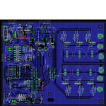
Here are the schematics and board design :
thank you all for your helpful replies
nverter.pngnvertersch.png
 

Status
Not open for further replies.

Similar threads

Part and Inventory Search

Welcome to EDABoard.com

Sponsor

Back
Top