Continue to Site

Welcome to EDAboard.com

Welcome to our site! EDAboard.com is an international Electronics Discussion Forum focused on EDA software, circuits, schematics, books, theory, papers, asic, pld, 8051, DSP, Network, RF, Analog Design, PCB, Service Manuals... and a whole lot more! To participate you need to register. Registration is free. Click here to register now.

Push-Pull Output not working?

Status
Not open for further replies.

karthickb3e

Advanced Member level 4
Joined
Dec 13, 2010
Messages
101
Helped
3
Reputation
6
Reaction score
3
Trophy points
1,298
Location
INDIA
Activity points
1,883
Hi all,

I am working for push-pull output. my rated current is 200mA..
i design the circuit as shown in below....

View attachment untitled.bmp
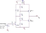
Push-pull Output stage Circuit.JPG

  • when my control input is low(0 volt) i want to sink...
  • when my control input is high(3.3 volt) i want to source...

But it does not work properly....

when my control input low, both pnp and npn transistor On , so the circuit gets damaged...

but for my control input high, the only pnp transistor gets On, and source properly to get my requierd output...
please give ideas to solve my problem.. or any working push pull output stage......
 
Last edited:

View attachment 70970
connect circuit like this....or place a diode between push pull tr base.

Thank you for your reply....
i tried your suggested configuration but, it not works?

---------- Post added at 09:43 ---------- Previous post was at 09:42 ----------

You could just try removing R8.

Keith

Thank you for your reply....
i tried with removing R8 but, it not works?

Any one please give me the working circuit.....
 

Must add apropiate load, able to source and sink current.
 

There should be a part of the cycle where the PNP transistor shuts off. This would be when input is low.

However it is not doing so. The voltage at its bias terminal needs to be raised higher during that time.

Try reducing the topmost resistor (R7) to 120 ohms. Increase R9 to 4700.

Also the load must somehow have V/2 applied at the opposite end, in order for push-pull current flow to take place through the load. Or install a series capacitor (per post #2). Or reconfigure the circuit to use a bipolar supply (+15 and -15).
 

My guess is you have not built it correctly. If you have removed R8 it will work. Does it work with no load? Where is your 200mA load connected to and what is it?

Keith.
 

My guess is you have not built it correctly. If you have removed R8 it will work. Does it work with no load? Where is your 200mA load connected to and what is it?

Keith.
Sorry iam not show load in figure ,,, but my load is resistive load....
 

I think your resistive load (maybe a resistor from output to ground) work good only for PNP transistor, source mode; you need another resistor to put from output to Vcc, to assure sink mode, which is done by NPN transistor.
 

You don't need to add a resistor to Vcc. If the load is to ground then your load will only take current in one direction. There is no requirement to take current when NOT driving the load. Why do you need a push pull driver? If it is simply a resistive load you could connect it to VCC and use one transistor to do the job.

You really need to simply fix what you have built and try it with no load.

Keith
 

Status
Not open for further replies.

Part and Inventory Search

Welcome to EDABoard.com

Sponsor

Back
Top