Continue to Site

Welcome to EDAboard.com

Welcome to our site! EDAboard.com is an international Electronics Discussion Forum focused on EDA software, circuits, schematics, books, theory, papers, asic, pld, 8051, DSP, Network, RF, Analog Design, PCB, Service Manuals... and a whole lot more! To participate you need to register. Registration is free. Click here to register now.

push-pull amplifier with output torroidal load

Status
Not open for further replies.

anne ranch

Newbie
Joined
Aug 8, 2021
Messages
4
Helped
0
Reputation
0
Reaction score
0
Trophy points
1
Activity points
31
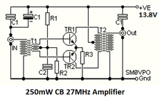
I understand that only one transistor conduct at a time .
The collectors are connected to start and end of the primary winding of the load.
The center tap is connected to power supply.

What is the direction of EACH part of the load coil ?

Usual "DOT" indicating start is missing from schematic .

Should "dot" be at the collectors ends - hence winding in OPPOSITE direction ?
Or should only ONE collector end have "dot" and the other "dot " being at center tap - hence both winding in SAME direction ?

Or does it matter ?

In theory only part of the wave is active and passed to secondary winding of the impedance transformer.
 

one collector to dot - the other not - it even rhymes ....
--- Updated ---

the Vin has one of each connected....
 

A tapped transformer winding symbol has implied polarity assignment (direction continuous from start to end) and doesn't necessarily need dots.
 

I am getting inferiority complex. Is my english so bad EVERIBODY wnats a pisture ?
Stand by untill l I figure how to include file here


This may be a dupe.

I have posted similar request to few forums and gotten nowhere.


Could somebody help me to add “dots” to both T1 and T2?

Both are torroids, but that may not matter.

Or just tell me if it does @ 14 MHz CW only?

But I feel it is important - if the T2 is wired wrong would it act sort of

doubler?
 

A tapped transformer winding symbol has implied polarity assignment (direction continuous from start to end) and doesn't necessarily need dots.
And does it apply to push -pull when each transistor passes only half of the wave ?
Should the wave appear (amplified ) SAME - with two half opposing each other , on secondary ?
 

The extremely old RF amplifier in the other forum does not have any negative feedback then the phases of the windings of the ferrite transformers do not matter.
 

You have been asking for push-pull amplifier, not doubler circuit. Push-pull means one transistor is generating the positive ouput wave, one the negative.
The collectors are connected to start and end of the primary winding of the load.
The center tap is connected to power supply.
You are starting the winding e.g. clockwise at one collector and continue til the other collector, with a tap in the middle. The winding instruction already defines a dot polarity. If you don't see, Easy peasy has clearly described the dot assignment. What's still unclear?

The pdf in post #6 seems empty.
 

Here is the schematic posted on the other forum:
 

Attachments

  • RF amplifier.png
    RF amplifier.png
    34.3 KB · Views: 111
T2 pri doesn't really need dots as it's drawn to show the connections very clearly, for the newbie:

If we say the TOP is a DOT or a START, then at the junction, in the middle, we have a NON-DOT or a FINISH, joining a DOT or START on the next winding down to a NON-DOT or FINISH as the bottom ....
 

Status
Not open for further replies.

Similar threads

Part and Inventory Search

Welcome to EDABoard.com

Sponsor

Back
Top