Continue to Site

Welcome to EDAboard.com

Welcome to our site! EDAboard.com is an international Electronics Discussion Forum focused on EDA software, circuits, schematics, books, theory, papers, asic, pld, 8051, DSP, Network, RF, Analog Design, PCB, Service Manuals... and a whole lot more! To participate you need to register. Registration is free. Click here to register now.

purpose of opamp in a REED SWITCH module

Status
Not open for further replies.
Hi,
LM393 is a comparator.

There are many different reasons why a LM393 is used. Terefore we need more information.

I'm sure you ask because you have seen this elsewhere. Tell us or show us where you found this.
Picture, schematic....
 

Hi,
LM393 is a comparator.

There are many different reasons why a LM393 is used. Terefore we need more information.

I'm sure you ask because you have seen this elsewhere. Tell us or show us where you found this.
Picture, schematic....
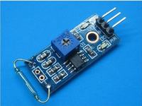
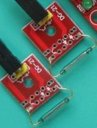
@KlausST thanks for replying. yeah you are right.Here are the two types of reed switch module. I understand the simple one , Connect one terminal of reed switch to GND and other with microcontroller. Simple interfacing like push buttons. I don't understand the one with pot and L393. What are the benefits and application? specifically where it is used and why does simple module can not be used for that application?
 

Without knowing anything about the module in the picture, a shot in the dark may be that it is an interface in a security application. The input is balanced and the reed switch may be part of a tamper protection.
2 comparators will typically form a window comparator. If the input impedance is inside a 'window' all is good, if it is too high, or too low, there is an alarm/ fault condition. Triggering the reed switch result in an alarm condition, like trying to open a connection box. This will remove the magnet from the switch and sound the alarm.
 
Alternatively, it may be that some other component could be connected instead of the reed switch. The PCB with polarity markings on it may be designed to take a different component, maybe an optical sensor or even a capacitor across the switch with the potentiometer used to set the output switching threshold.

Brian.
 
Hi,

Another possibility:
Maybe it sends out a frequency when switch is closed and another frequency when open. So it is more difficult to hack the signal lines.

A crystal ball is a nice toy....

Klaus
 
Hi ,
First of all I am extremely sorry for late reply. I would like to thank everyone.
After looking closely to both side of the PCB, I found one reason. The PCB used for this module was made for Hall Effect sensors/ IR receiver like that. Here in this particular case of reed switch the OPAMP is not used. What do you think ?
Again I am really really Sorry. I mean it.
 

Status
Not open for further replies.

Similar threads

Part and Inventory Search

Welcome to EDABoard.com

Sponsor

Back
Top