Welcome to our site! EDAboard.com is an international Electronics Discussion Forum focused on EDA software, circuits, schematics, books, theory, papers, asic, pld, 8051, DSP, Network, RF, Analog Design, PCB, Service Manuals... and a whole lot more! To participate you need to register. Registration is free. Click here to register now.
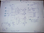
I have designed a circuit for Pure sine wave inverter of my own. Please find the attached image.
I request the experts out here to look over my design and comment with valuable suggestions.
1. you will get fewer switching losses if you use MOSFETs instead of bipolar output transistors.
2. unless for some EMC purpose, you don't need two inductors in series with the transformer primary, one will suffice.
3. I suggest the output relay is powered from the incoming mains and the contacts are also used to enable the inverter. Normally, two isolators are needed, one to disconnect the incoming power and one to connect the inverter output and there would be circuitry to ensure they could not operate simultaneously.
My plan is to use more MOSFETS parallel (say 3 or 4) in each section to carry the load according to the transformer size. "P90NF03L" is in mind to be used.
And, do you mean to use IGBT? actually whats the benefit using IGBT instead of MOSFET? I have no any idea about IGBTs.
As you suggested, I also think One inductor will suffice. Thanks for the point.
But when I look at some other circuits, no any inductor is used!! is that work good? can a normal iron cored transformer work with a pwm (high frequency like 16Khz).
Regarding the changeover relay, What I think is, even if the DC supply from battery (entire power supply for the circuitry) lost in any reason, the input Line will supply to load with out any circuit working.
---------------------
My plan is to use the same transformer for charging purpose too. the internal diodes of each MOSFET will form a rectifier and the MCU controlled relay will control the charging process.
Your schematic shows bipolar output transistors but it seems like you intended to use the MOSFET symbol instead. IGBT will also work, they are a hybrid of MOSFET and junction transistor but I'm not sure they would work any better than standard MOSFETs in that design.
The inductor probably isn't necessary at all, I assumed you added them as some sort of EMC protection. An iron core will work at 16KHz but it's efficiency will be lower than a ferrite core and it would be significantly heavier. I would use ferrite at 16KHz. You may need some filtering at the output side of the transformer to reduce residual 16KHz but leave the underlying 50/60Hz to pass through.
The point I was making about the relay is that a single changeover contact probably won't meet safety regulations. There are issues over the time it takes to disconnect the incoming power source if it fails. You have to consider what might happen if the unit supplied power back to the grid, even for a short period, it could be deadly to someone working on reparing the line. They would isolate the power feeding the line from the generator side but you could still push power up the line from your end.
Also be careful with using the diodes in the output devices as a bridge rectifier, their output may produce 12V which fools the inverter into starting up again. You need a fast acting shut-down that senses grid voltage is present and probably a short delay (a few mS) after sensing grid failure before enabling the inverter and relay.
IGBT's are very high speed 10~100ns, very high voltage 100V~3kV , low loss
MOSFET's are ~up to 600V, but low V are lower RdsOn than Rce of IGBT's
You can estimate your load impedance referred to bridge and decide how much loss you want then choose switch RdsON << this equivalent load. Look in the mOhm range, like a FAN7093 or better.
Friends… Let me explain a little about the control working what I planned in mind (Not yet written program)
Point “A” is connected to switching transistor for Changeover relay (40A+ rating)
Pont “B” also the same for Charger On/Off relay (10A rating)
Point “C” is an input to controller giving measurement according to the load hooked on the output
Point “D” also an input to tell MCU the main’s presence.
Let us assume Input power supply is there and battery connected. The MCU will do the following:
- It will not energies the Changeover relay. So the input AC line supply will go to Output terminal through NC part of the relay.
- MCU will monitor the voltage level of connected battery. If the battery voltage fall down to desired level to start charging, the relay placed for charging will be energized. In this time the diodes inside each MOSFET will act as rectifier diodes to form DC charge for Charging the battery. MCU will take care of safe charging (Not to go OVERCARGING).
- Through the point “C” MCU will get the information about the load connected in the output. MCU will only take this information in mind when the Inverter is working. If It overloads, the inverter will stop working and produce warning beep.
- When the MCU lost signal about the presence of Input supply, immediately will turn off the charging relay if it is ON. Then turn ON the changeover relay and then start the inverter. So now the output load connected to inverter.
If the MCU got any signal through point “D” about input power presence, will wait a little to ensure the supply is stable, then the inverter will turn OFF and the changeover relay will de-energize to connect the output load to input AC.
- - - Updated - - -
Mr Brian.... As you told, If I ignore the inductors used, the output will be a PWM. if I try to wipe out the 16kHz part, the wave will be a Sine wave. How can I achieve that? Capacitor? If so, If my plan is to use a transformer to carry 1000W load, what should be the value of that capacitor??... please explain on this...
An inductor alone in the primary side will not do the job adequately. An LC circuit in the secondary will work better. I'm away from my desk for a few days - perhaps someone else can help with the details.
This site uses cookies to help personalise content, tailor your experience and to keep you logged in if you register.
By continuing to use this site, you are consenting to our use of cookies.