Continue to Site

Welcome to EDAboard.com

Welcome to our site! EDAboard.com is an international Electronics Discussion Forum focused on EDA software, circuits, schematics, books, theory, papers, asic, pld, 8051, DSP, Network, RF, Analog Design, PCB, Service Manuals... and a whole lot more! To participate you need to register. Registration is free. Click here to register now.

[SOLVED] Pure sinewave inverter with toroidal transformer

Status
Not open for further replies.
On the other hand, if you start the SPWM at the 90 or 270 degree mark, then you expose all components to peak current abruptly.
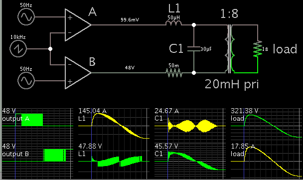
I presume Falstad doesn't use a saturable core in the standard transformer model (other circuit simulators do neither, and it's always a bit demanding to find the right core parameters if you use such a model).

But if you have a saturable core, then the sine voltage should be in fact started at 90 or 270 degree to avoid saturation (You want a symmetrical flux ∫Vdt, so you start with half the area). Of course this contradicts the idea of smooth filter capacitor start current.

So yes, a voltage ramp is probably the most simple solution. Alternatively, a fast saturation free start could use one halfwave of 50% magnitude and switch to 100% after the first zero crossing.
 

    V

    Points: 2
    Helpful Answer Positive Rating
So yes, a voltage ramp is probably the most simple solution. Alternatively, a fast saturation free start could use one halfwave of 50% magnitude and switch to 100% after the first zero crossing.

FwM:

I want to play safe so I have to ask it again: if I start with 0% then I increase the sPWM ratio with a factor of 2% during first 50 cycles (one second), there will be any problem? There might be a large load connected when I first start the inverter so I want to protect the MOSFETs as much as I could.
 

I already said it's a simple solution, which presumes that it works. For acceptable ramp rates related to transformer saturation characteristic, you have to refer to the exact transformer data, e.g. saturation flux, time constant L/R. I believe that 1 sec is slower than necessary.

The other point is load behaviour. Some loads may have problems with too slowly rising voltage.
 

As far as I can tell, Falstad's transformer is an ideal model. I looked in the source code but found nothing which suggests saturable core.

For the pursuit of curiosity, here is a simulation which starts the cycle at 90 degrees. Full voltage is applied for 1 mSec.


Ampere draw does not appear to spike. It climbs quickly to normal maximum.

Parasitic resistance is a big hindrance. I inserted a value of .05 ohm as a guess. But if it were, say 1/10 ohm, you'll have trouble getting sufficient current draw.
 

    V

    Points: 2
    Helpful Answer Positive Rating
Hi,

[QUOTEI want to play safe so I have to ask it again: if I start with 0% then I increase the sPWM ratio with a factor of 2% during first 50 cycles (one second), there will be any problem? There might be a large load connected when I first start the inverter so I want to protect the MOSFETs as much as I could][/QUOTE]

We developed a soft start unit tor an 8kVA transformer. Without softstart we saw up to 200A no load inrush current (@400V) and sometimes a 32A fuse switched off.
We decided to use a triac with increasing pwm. Additionaly we integrated the current of each halfwave (voltage controlled) and compared them to get saturation information. ( with saturation the current of one halfwave differs from the other).
With this information we compensated the saturation by slightely adjustin the duty cycle of both halfwaves.
The result was, that i've never seen inrush current of more than 500mA (no load current is about 450mA).
Pwm ramped up in about 500ms. It was a small and relatively simple HW solution.
It worked and still works better than expected.

******

Swithing on at 90 degrees works. Starting Pwm at 50% and then increasing theoretically also works.

For simulating in excel or so you could us the integral of input voltage to get a clue of the magnetism.
Starting at 90 degrees you see about no offset.
If you start at zero cross the magnetism signal has a large offset and about twice the peak value..
In reality the magnetism is additionall high pass filtered with a time constant (of several minutes in our case).

Klaus
 

    V

    Points: 2
    Helpful Answer Positive Rating
I've just got the toroidal transformer (a real "monster": 35 cm diameter, 40 Kg) so I'm ready to begin tests. Seems like starting at 90 degrees (max voltage) is the best solution.

Still I wonder if a custom pattern pulses (not sine PWM) could allow a better suppression of that inrush current (reading from the datasheet: 30 kA peak / 10 kA RMS!!). A burst of small pulses or something?

There will be the toroidal choke between H bridge MOSFETS and the toroidal transformer input (and maybe a capacitor too) so it will filter the pulses anyway. Seems like a complex situation though.

KlausST:

What you did with the PWM driven triac it's similar with sPWM driven H-bridge, right? Or do you recommend the triac solution?

BradtheRad:

Your simulation is great! When you and FwM agree about 90 degree startup there's no doubt this is the way. I just want to learn more about the core saturation process / inrush current, not to make any fatal mistakes.
 

90° start is only O.K. if the filter capacitors are small, as previously discussed. In so far the situation is probably different from the triac application.

I think all available options have been exhaustively discussed, it's your turn to implement an appropriate solution.
 

    V

    Points: 2
    Helpful Answer Positive Rating
Thanks, FwM! So I keep the regular sPWM pulses, starting at 90 degree (max voltage)? It's better to start with a lower PWM ratio (50%) or the regular one (95%)?

Anyway, I have to redesign the drivers/H-bridge first (for higher currents). In a day or two I could make the fist tests. Thanks everyone for all those precious informations!
 

Hi,

sorry, i don´t want to confuse you.

You don´t need triac. Just use it with your pwm if you think it is a benifit for you.

Klaus
 

I'm using Arduino DUE as MCU for generating the sPWM signal so I could easily make changes for any particular pulses pattern (if necessary) for the startup/shutdown process.
 

Hi guys,

I've just built a pure sinewave inverter (230V / 3kW) with a LF output transformer but I want to change the regular (EI) transformer with a real(!) one - a high efficiency toroidal type.

What do you expect would be the efficiency with your EI transformer? How much improvement do you expect with the toroidal transformer?

Have you made any measurements of the relevant parameters of both transformers? For example, what is the DC resistance of the primary and secondary windings of each transformer?
 
My new 5 kW rated toroidal transformer has only 25 W no load power consumption. You have to actually see it to understand that the primary (30 V) has no (measurable!) DC resistance - it has huge conductors (in fact, multiple thinner conductors in parallel). Efficiency, almost no flux dispersion and so on.
 

Your profile doesn't say where you live, but judging from the 230 volt output of your inverter, it isn't in the U.S.

You may not have noticed, but for some reason there has been a concentration of inverter manufacturers in the Pacific Northwest of the U.S.; Trace Engineering (sold to Xantrex), Outback Power, Magnum Energy, Heart interface (sold to Xantrex), Statpower, and Xantrex are some.

I live there and I've worked as a design engineer for two of them and consulted for some of the others. I can tell you about our designs for inverter transformers, what the design choices are and why they're made.

It's quite possible to measure the DC resistance of the primary; you just can't do it with an ordinary ohmmeter. What I do is to use a bench power supply with a current limit adjustment. Set the current limit to 1.00 amps, apply this 1.00 amp current to the primary and measure the voltage across the primary with the 1.00 amp flowing through it. The voltage is numerically equal to the DC resistance of the primary.

Here's a 4kW transformer used in one of the commercial products:


This transformer weighs 16 kg and has a no-load power dissipation (we call it idle power in house) of 9 watts. You can see the large copper primary tabs. The primary is wound with copper foil, although it's thick enough that it's more like copper sheet than copper foil, The primary DC resistance is 3.9 mΩ; the secondary DC resistance is 138 mΩ. We never use toroids because the cost/benefit ratio is not seen as favorable; they cost too much for a relatively small improvement in efficiency, although I think Xantrex is using one in a recent high-end design.
 
Well, I wasn't so lucky with my EI transformer. I actually had two of them (1.5 kW) parallel connected and they were using copper foil too (not so thick though). They were spare parts from two (broken) APC SmartUPS. Seems like they were designed for "15 min running" (UPS style).

Anyway, EI transformers have air gaps so their iron losses are significant. I really wonder how your transformer has such a small idle consumption - it must be a masterpiece.

As far as i read, EI transformers used in UPS/inverters have lousy windings (on purpose) to use their leakage inductance as a low pass filter (together with the output capacitor).

Anyway, I wasn't happy with my transfomers as I had to put a fan (always ON) to keep them cold even at no load and their output was very unstable with load variations.

My current toroidal transformer costs me almost 450 EUR (btw, I live in Europe) so I hope it's really worth the money. Being used by Xantrex in their high-end design it's a good news. ;)
 

Anyway, EI transformers have air gaps so their iron losses are significant. I really wonder how your transformer has such a small idle consumption - it must be a masterpiece.

It's true that the air gap in EI transformers is somewhat larger than in a toroid, but it's not a major contributor to losses. Perhaps you're thinking of high frequency ferrite transformers where the fringing flux from an air gap in the center leg causes eddy current losses in the nearby copper windings. In an EI transformer the laminations are interleaved in opposite directions and flux at the butt joints does pass through the neighboring lamination, causing the flux density to be higher in the immediate neighborhood of the butt joint. This does cause the flux density there to be higher than nominal, and therefore losses are somewhat higher there, but the volume of iron so affected is very small compared to the total volume of iron in the transformer.

The major contributor to iron losses is the quality of the laminations. We always use M6 laminations, but when we have asked for sample transformers from a possible new vendor in the far east, they sometimes try to pass off M19 or worse in the sample.

Inverter transformers are designed differently than others in that no load losses are so important that iron loss is minimized at the cost of greater copper loss. The total losses in the transformer pictured in the image above are somewhat over 200 watts at full load (compared to 9 watts no load); those losses are essentially all copper loss (the iron loss remains essentially a constant 9 watts) and a fan is definitely required!

We are aware that customers want higher efficiency at the same time as lower no load losses. These requirements are contradictory! One way to achieve this, other than using toroids, is to use M4, or even M3 laminations, but the cost of the transformer is then significantly higher.

The leakage inductance in an EI transformer has no copper loss (beyond the unavoidable copper loss in the existing primary and secondary winding), whereas the additional external inductor that is required with a toroid is wound with real copper and has core losses too. Those losses negate some of the efficiency improvement due to the use of a toroid. The transformer in the image above gives a total efficiency of about 92% for the inverter. It might go up to 94% or 95% with a toroid, but then the additional inductor losses might bring it back down to 93% or so. Not much overall improvement.

As far as i read, EI transformers used in UPS/inverters have lousy windings (on purpose) to use their leakage inductance as a low pass filter (together with the output capacitor).

EI transformers are constructed with concentric windings; copper foil on first and then the secondary. This leads to a leakage inductance that is just right for use with the filter action. Leakage inductance could be made much less with interleaved windings like they do in audio output transformers used with tube power amps; (secondary split into two halves with primary in between the two primary halves), but then the leakage inductance would be too low. An external inductor would then be required with its additional losses; not a good trade off! I actually had our transformer shop (when we had one) make a transformer in the split bobbin mode, with the primary and secondary side by side rather than concentric. The leakage inductance was much too high. The ordinary concentric winding method works out just right.

Another issue raised in this thread is power factor correction on the primary side. The "bad" power factor is due to the fact there is some lagging primary current due to the less than infinite primary inductance. The primary inductance in a typical inverter transformer is in the 10s or millihenries; the transformer shown in the image has 100 mH. The additional losses due to the small magnetizing current being out of phase is negligible. You don't want to have any additional capacitance across the primary winding because there are fast rising voltages applied there. The high dv/dt edges would cause large spikes of current in an added capacitance, with attendant losses and EMI production. The filtering to get rid of the high frequency components of the SPWM waveform should be on the secondary side. A suitable inductor on the primary side would have be wound with large wire or foil to carry the high primary current with its attendant proximity losses in addition to the ordinary I²R losses.

My current toroidal transformer costs me almost 450 EUR (btw, I live in Europe) so I hope it's really worth the money. Being used by Xantrex in their high-end design it's a good news. ;)

I'm unaware of transformers suitable for inverter use being available as a standard item from transformer vendors. Usually the transformers have to be custom designed for proper turns ratio and other important parameters. Is the toroid you bought designed specifically for inverter use? Can you provide a link to the manufacturers web site? I'd like to have a look at their product line.

A commercial inverter is expected to provide a surge of at least 2 times the continuous rating for a few minutes. To do this, plus to provide high efficiency, the H bridge is composed of a number of paralleled FETs in each leg of the bridge. Modern FETs used in this application are typically capable of 100 amps continuous each. If there are, say, 5 such FETs in each leg then 500 amps continuous (more for a few tens of milliseconds) won't hurt anything.

The internal resistance of a bank of L16 batteries, for example, plus the resistance of the cabling, the FETs, the DC resistance of the transformer, etc., will limit the start up surge to several hundred amps max. We don't do anything special to deal with a start up surge; just let it happen.

Your toroid will only see inrush current like this: "(reading from the datasheet: 30 kA peak / 10 kA RMS!!)." when connected to something capable of supplying 10 kA--something like the grid.
 
Plenty of good informations - thank you very much!

First, my toroidal transformer was custom made (special for inverter application). Its primary winding (30 V) has been made of some sort of litz wire - many thinner wires in parallel, for skin effect resistance (copper foil isn't an option with circular toroids).

Regarding the H bridge.. yes, I'll be using 6 MOSFETs (130 A rated) in every leg so almost 800 A continuous.

My battery string has over 1 kA starting current so that may be a problem. ;)

About high frequency filtering.. isn't a toroid inductance (choke) in series with the primary winding a solutions, as discussed before? And the capacitor might be eventually located across the secondary?
 

" We always use M6 laminations, but when we have asked for sample transformers from a possible new vendor in the far east, they sometimes try to pass off M19 or worse in the sample."

I have had the opposite problem. For validation and certification, they provide a transformer with the optimal materials.

Once that the product has been validated and certified, and actual production shipments start, they start to degrade the transformer...slowly. For instance, they'll reduce the copper half an AWG gage. They will start interleaving M19 material with M6 material. If you don't notice the incremental degradation, they will continue the practice until there is a complaint, at which point they'll back off.

Some of them are actually quite smart in their cheating. Once we had a transformer with higher DCR. First suspicion: the wire gage. Careful measurement with an optical comparator yielded spot-on wire diameter. Disassembling the transformer yielded almost identical wire length of a good transformer.
We were going crazy until someone suggested a chemical analysis of the wire itself. Electrical grade copper is 99.9% pure, as any impurities quickly degrade conductivity. Refining copper to such purity is a significant cost increase.

Turns out they were using 98% pure copper. Clever, very clever the way the cheat.
 
0.5 sec to 1 sec is a good starting point for a soft start on the inverter o/p
 

My battery string has over 1 kA starting current so that may be a problem. ;)

Is this a value you've actually measured, or is it a manufacturer's spec? The FET spec (transient thermal impedance) should show that a current 2 or 3 times the continuous rating can be carried without damage for several tens of milliseconds. Of course, to do this, the gate drive must be nearly the maximum allowed to insure that the FET is fully on, and negative drive at turn off to make sure the voltage spike on the drain doesn't turn the FET back on through the Miller capacitance.

We had a test jig that could pass 500 amps through one of our FETs for 8 milliseconds without damage. That's how we could tell whether the FET manufacturer was trying to pass off a chip shrink as equal to the earlier FET design with a larger chip.

About high frequency filtering.. isn't a toroid inductance (choke) in series with the primary winding a solutions, as discussed before? And the capacitor might be eventually located across the secondary?

I see no advantage to using an inductor on the primary side. It has to carry a much higher current than secondary side current would be, and unless special wire (litz) is used, proximity effect losses are likely to be high. Why not use a secondary side inductor? The capacitor should be located on the secondary.

Currently, the local inverter folks provide a "low idle kit" consisting of a small saturable toroid with the primary making a single turn through the toroid, but this doesn't do anything as soon as much load is applied.

- - - Updated - - -

" We always use M6 laminations, but when we have asked for sample transformers from a possible new vendor in the far east, they sometimes try to pass off M19 or worse in the sample."

I have had the opposite problem. For validation and certification, they provide a transformer with the optimal materials.

Once that the product has been validated and certified, and actual production shipments start, they start to degrade the transformer...slowly. For instance, they'll reduce the copper half an AWG gage. They will start interleaving M19 material with M6 material. If you don't notice the incremental degradation, they will continue the practice until there is a complaint, at which point they'll back off.

Some of them are actually quite smart in their cheating. Once we had a transformer with higher DCR. First suspicion: the wire gage. Careful measurement with an optical comparator yielded spot-on wire diameter. Disassembling the transformer yielded almost identical wire length of a good transformer.
We were going crazy until someone suggested a chemical analysis of the wire itself. Electrical grade copper is 99.9% pure, as any impurities quickly degrade conductivity. Refining copper to such purity is a significant cost increase.

Turns out they were using 98% pure copper. Clever, very clever the way the cheat.

Wow! I never had an overseas vendor try this sort of skulduggery on me. Fortunately, most of the time we were making our own transformers.
 

Is this a value you've actually measured, or is it a manufacturer's spec?

How to measure that?! (1000 Amps limit) Those are heavy duty truck batteries and that's what the manufacturer claims about them.

I see no advantage to using an inductor on the primary side. It has to carry a much higher current than secondary side current would be, and unless special wire (litz) is used, proximity effect losses are likely to be high. Why not use a secondary side inductor? The capacitor should be located on the secondary.

I always thought that a low frequency transformer (EI or toroidal) should never "see" such a high frequencies (5 - 20 kHz). Beside, in every LF specifications I saw the maximum working frequency of 400 Hz or so.

If I put the toroidal choke on the output, all the high frequencies will pass the transformer. There will be no problem ar all? BTW, I've just made a test with my actual inverter (with EI transformer). I put a 50 Amps (litz wire) choke in series with primary (low voltage) and I found out that the high pitch noise of the transformer has almost disappeared. I didn't have time to check the waveforms with the oscilloscope but I could imagine that the parasitic HF has been drastically attenuated.

Of course, you have infinite more experience with such a things but I wanted to tell you about this facts. Of course is more desirable to put a smaller choke at output but I just don't know what's the catch.

Currently, the local inverter folks provide a "low idle kit" consisting of a small saturable toroid with the primary making a single turn through the toroid, but this doesn't do anything as soon as much load is applied.

Speaking of diy folks, that's the old **broken link removed** about toroid modification (quite empiric I may say). That's where I first read about that mighty choke.
 

Status
Not open for further replies.

Similar threads

Part and Inventory Search

Welcome to EDABoard.com

Sponsor

Back
Top