Continue to Site

Welcome to EDAboard.com

Welcome to our site! EDAboard.com is an international Electronics Discussion Forum focused on EDA software, circuits, schematics, books, theory, papers, asic, pld, 8051, DSP, Network, RF, Analog Design, PCB, Service Manuals... and a whole lot more! To participate you need to register. Registration is free. Click here to register now.

PURE SINE WAVE INVERTER using ir2110

Status
Not open for further replies.
You may want to generate the deadtime in front of IR2110.

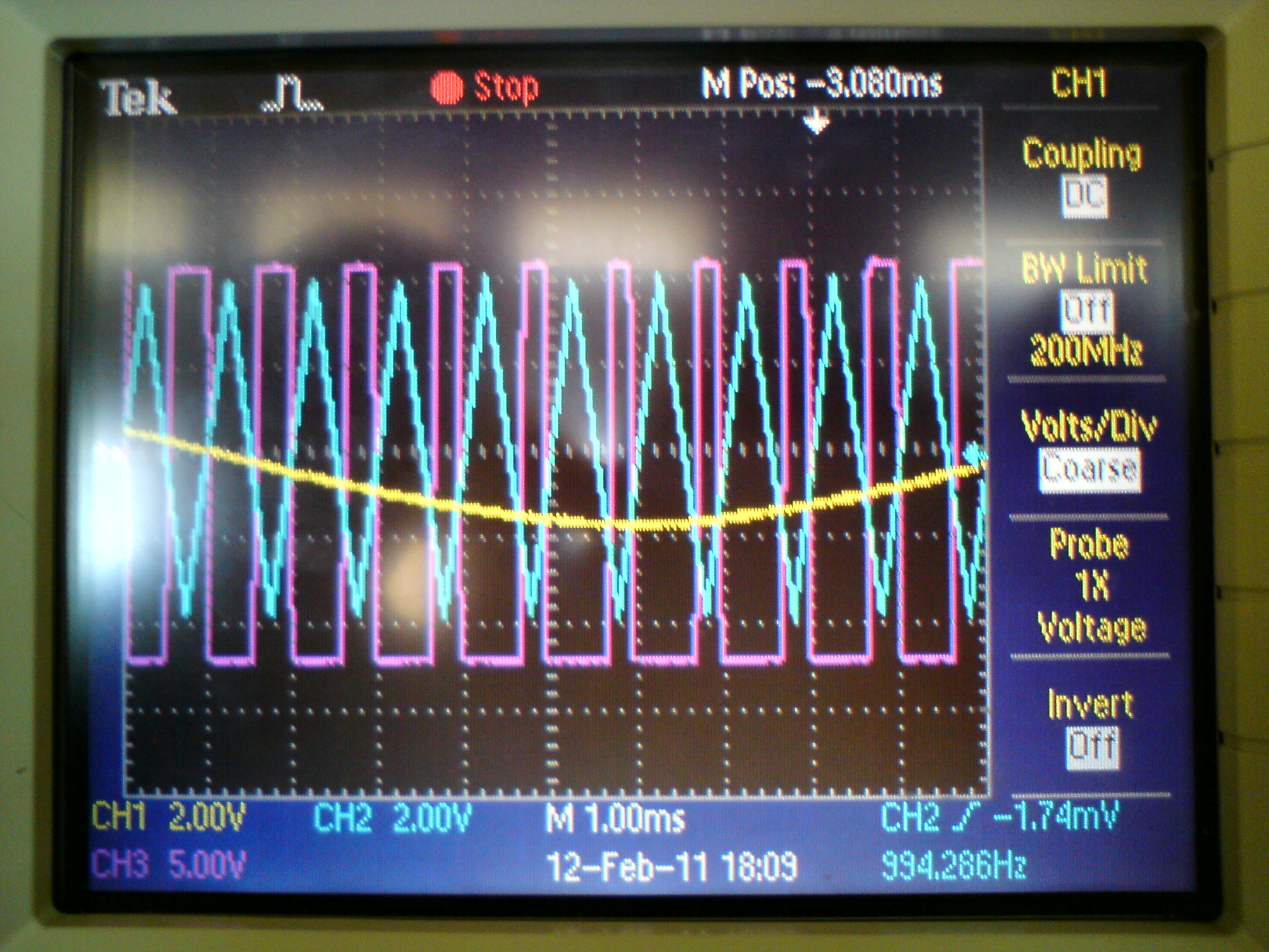
are you referring to rcd deadtime? did it. but no good. more deadtime makes the output wave less and less sine-looking so i have to limit the deadtime generated.
 

You have told, that the deadtime generated by IR2110 would be insufficient, so I suggested to add it externally. In fact, your assumption may be wrong, but I'm not able to check it from a distance. Generally, generating the low side and high side control signal in software separately gives you any required degree of freedom.
 

hello
i am making an 12vDC/220vAC inverter
i use two ICL8038 function generator ICs to generate sin and triangle wave the i compare between them using a comparator as shown


any notes about the image ??

1) i want to know how to use this output signals to drive the HIN and LIN pins in the IR2110
2) please i want to know what is the better between
a) making 12vDC/12vAC inverter then stepping up the output 12vAC to 220vAC using transformer
b) step up the 12vDC through high frequency transformer then make the inverter stage
and why??
thanks
 

You have told, that the deadtime generated by IR2110 would be insufficient, so I suggested to add it externally. In fact, your assumption may be wrong, but I'm not able to check it from a distance. Generally, generating the low side and high side control signal in software separately gives you any required degree of freedom.

By saying adding the deadtime externally, do you mean adding resistors, capacitors, and diodes for both the Hi and Lo input signals? Can you please enlighten me more about using software to generate Hi and Lo signals? Havent done it yet.
 

Hi,you can simply achieve that by using two op-amp,you
Can used the inverting input of the first op-amp and non inverting of the second op-amp by applying a refrence voltage and let's say +5v,then the second op-amp inverting and the first op-amp non inverting are connected to pwm signal so that the output will be out of phase with the other,i will try and draw the circute diagram for you if I am less busy.
 

Can you please enlighten me more about using software to generate Hi and Lo signals?
Most people are using e.g. PIC processors for PWM generation. You can find masses of references at edaboard. Basically, deadtime is a software parameter with this designs.

I didn't notice that you referred to an analog PWM generator with OP in a previous post. In this case, resistors, diodes and capacitors are the way to go. Nearly everything can be achieved with it. The problem is however, that you should have an idea of the intended gate waveforms and that you are able to check the results with an oscilloscope.
 

thank u kabiru
but what about the second question??
 

what about the second question
There's no better one. Both solutions exist on the market, the high frequency DC/DC solution is spreading however.

It's a tradeoff between transformer weight and electronic parts BOM. Personally, I won't suggest the DC/DC solution for a DIY design, unless you have sufficient experience with fast high power switching and the necessary measurement equipment.
 

This depend on your desinge,if you need your inverter to be very compact then you can used the boost converter topology and the component are going to be much,but if you are using iron core transformer it will also work fine but it's going to be very big but less component so it only depend on your desinge.
 

thanks all
1) in case of using 12vDC/12vAC inverter then stepping up the output 12vAC to 220vAC using transformer
this means that if the output load take 1A, A 18.33A will pass through the 12vAC side
Are there any transformer that can withstand that condition??

2)for the boost converter
Can the boost converter be able to convert 12vDC to 311.13vDC which be able to get 220vAC by the inverter??
Are there any limits for the voltage gain??

3)for the other topologies
i know a lot of this topologies such as flyback,push-pull,half bridge,and full bridge converters
i think that the push-pull converter is the best choice, isn't it??
My problem is in the high frequency transformer
i release a HF transformer from my old computer power supply but i can't deal with it
where is the primary and secondary windings?? Are there any center taps??
this is the image of my HF transformer

thank u in advance
 

Most of us have reliable electricity so we don't use an inverter. A few people go camping, hunting or fishing then they buy an inexpensive inverter that has all the hard to find special parts in it.

Where are you going to find a small ferrite core for the high frequency transformer? Do you know how to design a high frequency transformer? Or will you use a big, heavy and expensive low frequency transformer? Or will you buy an inverter and use its parts in your own circuit?
 

1)i get my HF transformer from my old power supply
2)i don't know how to design a HF transformer
3)i may use heavy low frequency transformer but can i use it in my condition (12/220 transformer "this means that if the output load take 1A, A 18.33A will pass through the 12vAC side")
4)i will not buy an inverter and use its parts in my own circuit
please help me in my previous 3 questions.
thanks
 

Your questions about the dísmantled inverter transformer are showing, that you are effectively clueless about transformer basics. So how to help from a distance?

With some knowledge about transformers (and some minimal equipment), you would be able to measure most relevant parameters. But design of a high frequency inverter still isn't easy and probably won't succeed at first attempt. Without sufficient knowledge, failure of the project is a likely result.

The hidden transformer parameters to reveal are:
- internal circuit + windings resistances (would already answer several of your previous questions), simple to achieve
- windings ratio and absolute number of turns (this is an AC measurement, some more equipment is needed. Absolute number of turns can be easily determined, if you find a place for a single thin wire test winding)
- primary inductance
- air gap, if not visible, it can be estimated from point 2 and 3.
- core data, must be estimated from common power ferrite material datasheets

Having this data, you are able to determine, if the transformer is suited for the application.
 

Mayber a low frequency mains transformer connected in reverse to stepup the voltage will not pass the high frequency PWM waveform for a pure sine-wave inverter?
 

Please...I have the same questions as Hassan_zytoon....so I want a clear answer about this questions from anyone who can answer them.

Thanks
Khaled
 

try another type of MOSFETaside from ir2110..

---------- Post added at 20:14 ---------- Previous post was at 20:04 ----------

try using irf5210..i had an experience using that kind of MOSFET.
 

Question regarding TRANSFORMER:

Everyone suggests a Ferrite Core High Frequency Transformer for PWM-based Sine-Wave Inverters, but I am confused because I read somewhere that these transformers operate best at their resonant frequency (which is very high, above 20KHz) so they cannot be used to step up a high-frequency PWM having a 50Hz sine-wave embedded into its varying duty cycle.

I have the following waveform at the output of my Full-Bridge:


Pls guide me if I can use this kind of transformer with this or not. Another suggestion made to me was to use Medium Frequency Transformer (which works at 50Hz as well as upto about 8KHz).

Thank you.
 
Cheap Chinese pure sine-wave inverters use a DC to DC converter operating at a high frequency and using a small, lightweight and inexpensive ferrite-core transformer. Then they use high voltage Mosfets to produce the high frequency PWM waveform.
 
  • Like
Reactions: farjad

    farjad

    Points: 2
    Helpful Answer Positive Rating
Status
Not open for further replies.

Part and Inventory Search

Welcome to EDABoard.com

Sponsor

Back
Top