Continue to Site

Welcome to EDAboard.com

Welcome to our site! EDAboard.com is an international Electronics Discussion Forum focused on EDA software, circuits, schematics, books, theory, papers, asic, pld, 8051, DSP, Network, RF, Analog Design, PCB, Service Manuals... and a whole lot more! To participate you need to register. Registration is free. Click here to register now.

Pure Sine Inverter - topology question

Status
Not open for further replies.
R

red_alert

Guest
Hello,

I wonder if one could build a pure sine inverter using a single stage DC-AC converter.

The classical implementation is to build a DC-DC converter (24V -> 350V in my case) then use a sPWM driven MOSFET full bridge to get the 230V AC output.

My question is: can I use a single full bridge stage (sPWM driven) to convert a 24V ("bus") input to a 230V AC output?

Actually, instead of driving the classical DC-DC (24V -> 350V) converter with a simple PWM signal, could I use a sine modulated PWM signal to get the AC output voltage directly?

I've seen this implementation in LF output transformer inverters; they convert 24V DC to 16V AC which feed a standard low frequency (50Hz) transformer to get the 230V AC output.
 

Hi,

Like you say in your last sentence: It is possible, but you need a transformer with full power and lowest_desired_frequency rating.

Klaus
 

To get the 16V AC from the 24V DC battery, you need a simple sPWM driven full bridge + ferrite inductor + capacitor.

What if, instead of that ferrite (choke) inductor you're using a step-up ferrite transformer, to get a much higher output voltage (230V / 50Hz), so you don't need a LF transformer anymore?

What's the catch??
 

Hi,

The inductor doesn't act like a transformer. It only acts as a part of a lowpass filter.
If you put a transformer and measure the secondary voltage with a scope you will see high frequency spikes instead of low frequency sine.
You really get all the frequencies you dont need.

This idea wont work.

Sorry
Klaus
 

You still can use a step-up HF transfomer and put a LC lowpass filter at its output.

But, after further researching, I guess the problem is the working frequency ranges.

The boost converter works at higher (fixed) frequencies (50-200kHz) and the DC-AC converter works at lower frequencies (5-15 kHz, modulated by a 50/60 Hz signal). Maybe it's impractical to modulate a 150 kHz frequency with such a lower (50 Hz) modulating one. Or, if you're using a HF step-up transformer, the modulating process generate amplificated spikes (n1/n2) at the transformer's output.

Ok, so you need a separate DC-DC and DC-AC converter stages for a (LF) transformerless design.

I want to ask you another question: if I'll go with a LF output transformer design, could I use an already built welding transformer?

Reading the specifications, it could output 20V / 100A at full load (230V input). Using a DC-AC converter, I could get 12VAC from the 24V battery string. So theoretically I'll need a 12V -> 230V transformer.

BUT.. every (big) welding transformer has an 400V AC separate input. So if you feed it with 400V AC you'll get 20V / 100A at it's output. The reverse process being similar, that means if you're feeding it's "ouput" with 20V you're getting 400V at the "input".

Now, if you feed it with 12V AC, math leads to 12 * (400/20) = 240V (AC). So I get 230V (2-3 kW) without modifing the welding transformer.

It that correct? Are the welding transformers a feasible solutions? I was thinking of a bigger transformer (10KVA) because their normal duty cycle it's about 10-20%, so for a continuous 2kW output I think it's a fair solution.
 

Hi,

A welding transformer has special core parameters to make the output voltage weak. I think you don't want this.

I have a transformer (NOS) with 400V to 35V at 8kW to sell. 65kg. But i think 35V is too much for your application.

Hope this helps
Klaus

- - - Updated - - -

Hi,

A welding transformer has special core parameters to make the output voltage weak. I think you don't want this.

I have a transformer (NOS) with 400V to 35V at 8kW to sell. 65kg. But i think 35V is too much for your application.

Hope this helps
Klaus

- - - Updated - - -

Hi,

A welding transformer has special core parameters to make the output voltage weak. I think you don't want this.

I have a transformer (NOS) with 400V to 35V at 8kW to sell. 65kg. But i think 35V is too much for your application.

Hope this helps
Klaus
 

Thank you for your offer, Klaus! Actually, I already have that welding transformer so I can make some tests.

The truth is I prefer the high frequency DC-AC converter as a final stage (350V DC -> 230V AC) but I've just read some facts about the (possible) DC bias at the AC output as there's no transformer but just a plain inductor (choke). Maybe there's a way to avoid that by sensing the output current across that inductor (searching for zero point) and correcting the duty factor for every half of the full bridge.
 

Hello,

I wonder if one could build a pure sine inverter using a single stage DC-AC converter.

The classical implementation is to build a DC-DC converter (24V -> 350V in my case) then use a sPWM driven MOSFET full bridge to get the 230V AC output.


My question is: can I use a single full bridge stage (sPWM driven) to convert a 24V ("bus") input to a 230V AC output?

Actually, instead of driving the classical DC-DC (24V -> 350V) converter with a simple PWM signal, could I use a sine modulated PWM signal to get the AC output voltage directly?

I've seen this implementation in LF output transformer inverters; they convert 24V DC to 16V AC which feed a standard low frequency (50Hz) transformer to get the 230V AC output.

it is possible to do 16 vac from 24 v dc and then getting 230vac from 16 Vac with a transformer.
as far as i know the idea behind doing 350vdc from 24 v dc and then 220 v ac from 350v dc is just to use a smaller much smaller transformer.

because u can do a dc dc converter (24vdc to 350vdc) working 20-100khz with a small transformer. but u can not do a 16 vac to 220 vac with using a small transformer since your frequens is just 50 hz.
 

Now, if you feed it with 12V AC, math leads to 12 * (400/20) = 240V (AC). So I get 230V (2-3 kW) without modifing the welding transformer.

It that correct? Are the welding transformers a feasible solutions? I was thinking of a bigger transformer (10KVA) because their normal duty cycle it's about 10-20%, so for a continuous 2kW output I think it's a fair solution.

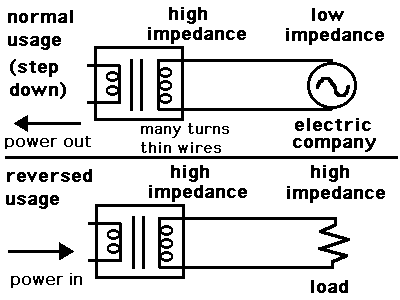
It would seem that the same watts should go in either direction...
However I tried a similar project, and I got disappointing output.

I did not understand why, and I wondered about it for a long time. Here is my best guess as to what happens.

9560323000_1399003686.gif


Normal usage:
The high-V side has to be high impedance. It is attached to the electric company (low impedance). So the high-V side has many turns of thin wires.

Reverse usage:
We wish to attach a load (high impedance) to the high-V side. But the high-V side is high impedance. The result is small current flow.
 

I'm still looking for a workaround here..

I've encountered some problems trying to design a full bridge DC-DC converter (24-350V) using a ferrite core transformer.

I've just found out an alternative way to get 350V DC without making use of transformers - that's a two-phase synchronous boost converter.

The only downside so far is the lack of insulation between the input (batteries) and the output (230V AC voltage) if I'm going to use a classical sPWM driven full bridge DC-AC converter.

Is there a feasible method to insulate the AC ouput from the 350V DC bus in this situation?


PS: There comes in mind my previous idea: the use of a 1:1 ratio ferrite transformer in a sinePWM driven full bridge stage followed by a 50 Hz LLC filter to get the 230V AC output voltage - but I've never seen it implemented yet.
 

A 24 to 350 V boost converter can be expected to have pretty much switching losses. Switching losses are rougly proportional to switched power, and switched power of a boost converter is about input current multiply output voltage.

A transformer based converter will score of a boost converter in terms of efficiency.

There comes in mind my previous idea: the use of a 1:1 ratio ferrite transformer in a sinePWM driven full bridge stage followed by a 50 Hz LLC filter to get the 230V AC output voltage - but I've never seen it implemented yet.

Don't know which topology you imagine. The output of a PWM circuit has low frequency components and needs a transformer designed for 50 Hz. You need at least a commutator bridge at the secondary side.
 

I've read that a two-phase synchronous boost (buck) converter could reduce the magnetic losses up to 10% of a standard (single phase) boost converter. A boost converter has only one switching element anyway - aren't the switching losses smaller than a full bridge topology?

And, by the way.. the switching frequency of a two-phase boost converter could be as low as 20 kHz or something (though the output capacitor sees two times the switching frequency).

==

Anyway, I have another topology question: I have four smaller LF-transformer based UPS. May I build a bigger inverter using those LF transformers?

May I put them in parallel (primary/secondary) if they are almost identical (same manufacturer/model)?
 

In electrical power engineering, the rule for transformer parallel connection is:
- same winding ratio (open circuit voltage)
- same Xeq and Req (leakage inductance and winding resistance, relative to rated power)

This can be verified in case of doubt.
 

    V

    Points: 2
    Helpful Answer Positive Rating
Thanks, @FvM, that's the way to go! The transformers are identical (same product code) so the parameters should be close enough.

I have one big question to you: could you help me to design (or point me out to some links) the output filter of the DC-AC converter?

The input voltage will be 21-29V (battery bank) and the output should be 14-15V AC. The rated input/output power should be 3 kW or so.

I choose a full bridge topology, using MOSFETs as power switches (Imax=280A, Rds=2mOhm), IR2110 as MOSFETs drivers and Arduino as sPWM signal generator (50Hz/20kHz).

There comes the LLC filter (to smooth the 20kHz chopped 50 Hz sinewave). I already have two big sendust toroid cores (ARNOLD) but I didn't find any formulas to calculate the inductances and the capacitor for this filter.

Thank you very much for your help.
 

As a first step, I would try with no primary filter at all, using transformer Ls as only filter inductance and possibly a secondary parallel capacitor. Calculate or measure if the switch frequent ripple current is still acceptable and don't cause too much skin effect and core losses in the transformer.

If you decide for a LC filter, keep it small by using a high cut-off frequency, e.g. 2 to 10 kHz, inductance with 2 to 5 % Xeq at 50 Hz (inductive voltage drop at rated current relative to operation voltage).
 

    V

    Points: 2
    Helpful Answer Positive Rating
Anyway, I have another topology question: I have four smaller LF-transformer based UPS. May I build a bigger inverter using those LF transformers?

May I put them in parallel (primary/secondary) if they are almost identical (same manufacturer/model)?

This simulation demonstrates how it could work.


The 'clock' is supposed to be AC square waves from a full H-bridge.

The LC series filter is a common tactic for turning square waves into sine waves (approximately). The L and C values need to be adjusted for the frequency and load. If the load is variable, then a different wave-shaping technique may be necessary.
 

    V

    Points: 2
    Helpful Answer Positive Rating
Thanks for the simulation! Unfortunately, the secondaries have to be in parallel, too (their output voltage will be 230V).

Anyway, to minimize the standby losses (the load is variable, indeed - various home appliances) I think I'm going to use multiple H-bridges (for every transformer or for every pair of transformers) and inhibit all branches but one during normal use. If the output current rises (heavier load) I'll wake-up another H-bridge to withstand the situation and so on.

The transformer's secondaries will be in parallel, but I'm going to put a triac in series with every secondary windings and turn on the triac only when the wake-up event arise.
 

Status
Not open for further replies.

Similar threads

Part and Inventory Search

Welcome to EDABoard.com

Sponsor

Back
Top