--BawA--
Advanced Member level 1
- Joined
- Nov 28, 2012
- Messages
- 479
- Helped
- 43
- Reputation
- 86
- Reaction score
- 42
- Trophy points
- 1,318
- Location
- Noida, INDIA
- Activity points
- 4,926
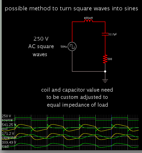
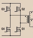
i have made an inverter using linear topology ,12vdc to 220vac 100va ,,but it produce square wave of 50hz,, i want to know how to convert this square wave into pure sine wave (using reference sine wave),,please help me ,,i have searched on internet alot,but didn't find any useful data...