Continue to Site

Welcome to EDAboard.com

Welcome to our site! EDAboard.com is an international Electronics Discussion Forum focused on EDA software, circuits, schematics, books, theory, papers, asic, pld, 8051, DSP, Network, RF, Analog Design, PCB, Service Manuals... and a whole lot more! To participate you need to register. Registration is free. Click here to register now.

Pure sin wave inverter

Status
Not open for further replies.
hi tahmid, i am using non polarised box capacitor in my filter design,
this is my schematics final1.png
i have reffered your blog for my hbridge design,,
i am writing some different cases which i have experimented and got failure
case1 - i have connected my hbridge to 32vdc and there was also lc filter in output ,,, in this case my circuit is working properly and i am getting the sine wave ,here is the image20130625_155952.jpg20130625_155702.jpg

case2- when i connect my hbridge to 311v dc bus, and filter is not connected,then there is no damage to mosfets,,i have also run resistive loads ,,

case3- when i connect hbridge to 311v dc bus and filter is also connected ,,,as i turn on my circuit ,my mosfets of hbridge blown out,,
my inverter rating is 350va, 220v 50hz,,
output filter rating - L=5mh (etd39 gapped core is used) and C=0.22uf
here are some more images of my circuit
20130625_162413.jpg
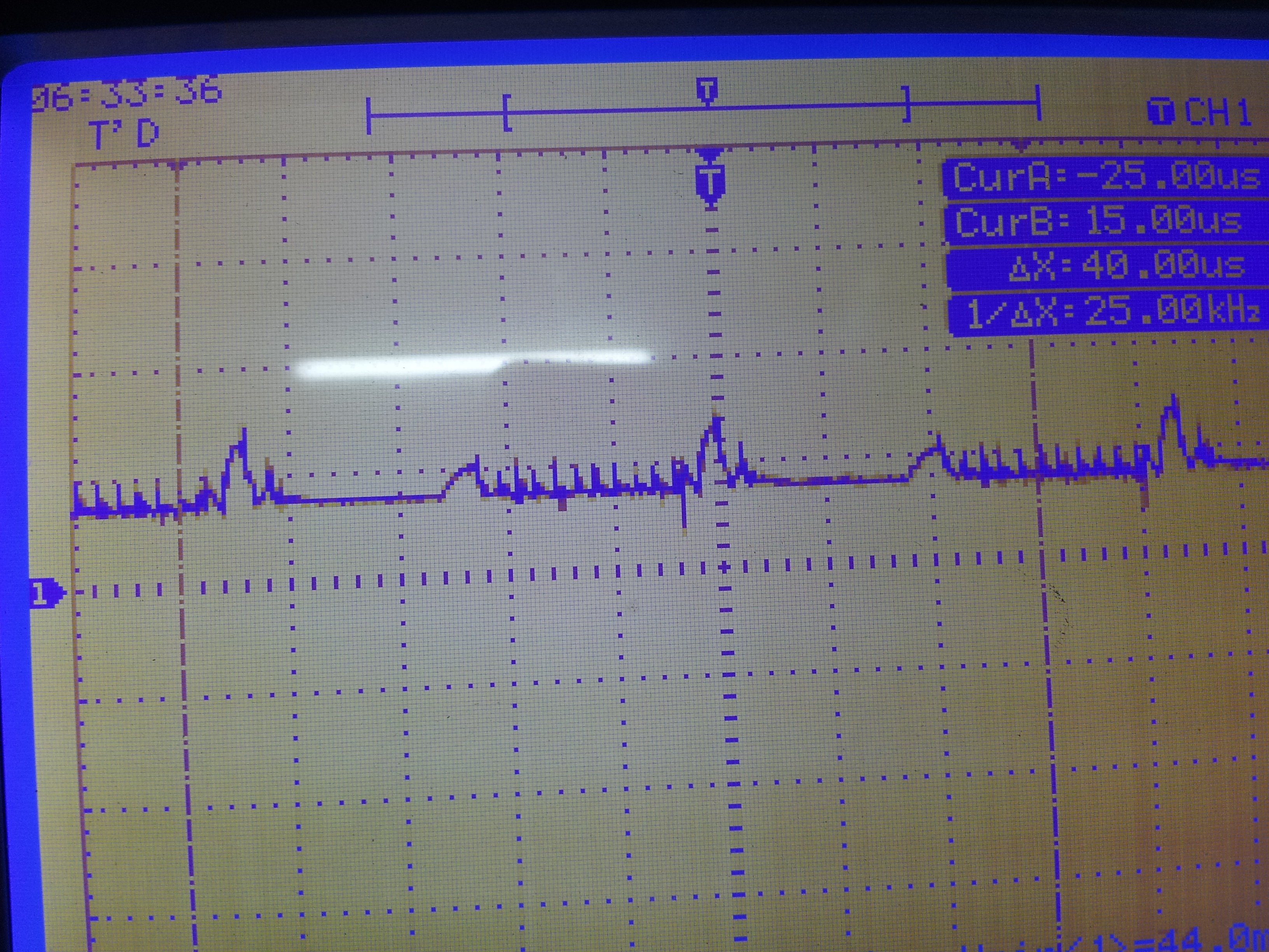
below is my spwm signal
spwm1.png
also proper dead time is provided between the signal
plese help me tahmid,,i have tried many times ,but didn't get success,,please tell me the problem?
 
Last edited:

I can't clearly think of any particular reason why this is happening. So, let's go step-by-step and try to figure out what's happening where.

1) Where is the 311VDC coming from? Is it rectified from the mains? Did you use a sufficiently larger capacitance to filter it to produce clean DC?

2) What is the voltage rating of the 0.22µF filter capacitor?

3) When the MOSFETs blow out, do they get very hot?

4) Do all the MOSFETs get damaged or is it just one or two or three? Which ones?

5) Did you test with no load? Or did you use a load? If so, what load?

6) Try adding a soft-start to the program so that the microcontroller starts sending the pulses a while after power is turned on.

7) Did you replace the filter capacitor and the MOSFETs and try again?

8) Add capacitors (filter and decoupling) across the VC and COM of the IR2110s, as well as between VDD and VSS lines of the microcontroller.
 
thanks tahmid for reply
Tahmid said:
1) Where is the 311VDC coming from? Is it rectified from the mains? Did you use a sufficiently larger capacitance to filter it to produce clean DC?
311vdc is coming from another circuit that i have already made,it is regulated. i have used 47uf capacitor ,here is the image
9685168800_1372179849.jpg

one more thing i have noticed,when i apply 311vdc to hbridge and filter is not connected ,then there is no damage, as i connected my filter (lc 5mh, 0.22uf) and switch on my dc supply mosfets of hbridge blown out also the mosfets which were used in dc dc converter stage also blown out.

Tahmid said:
2) What is the voltage rating of the 0.22µF filter capacitor?
on the capacitor it is written 1000v.

Tahmid said:
3) When the MOSFETs blow out, do they get very hot?
as i connect filter and switch on my dc bus bus, mosfets blown out,,, and also they get very hot.

Tahmid said:
4) Do all the MOSFETs get damaged or is it just one or two or three? Which ones?
i dont think that all mosfets of hbridge get damaged ,,only two of them get very hot,,i m not sure whether it was high side or low side,,,but probably it was high side mosfet that gets hot

Tahmid said:
5) Did you test with no load? Or did you use a load? If so, what load?
I have tested it in both conditions separetly that is with load (60 watt bulb) and without load also. in both conditions i have got failure.

Tahmid said:
6) Try adding a soft-start to the program so that the microcontroller starts sending the pulses a while after power is turned on.
In one trial I first turned on my microcontroller and then i switched on my dc bus,
in second trial i connected my complete circuit i.e. i have connected my dc bus to hbridge stage and simultaneously switch on the complete circuit (hbridge+dc dc stage),,
i haven't tried giving dc to hbridge first and then turning on my microcontroller.
Tahmid said:
7) Did you replace the filter capacitor and the MOSFETs and try again?
yes tahmid ,i have replaced my mosfets as well as filter capacitor,, infact this is my 16th try of complete circuit, but i have repalced my capacitor only 3 times,,after that i only replaced the mosfets (all four mosfets) and use the same capacitor.

Tahmid said:
8) Add capacitors (filter and decoupling) across the VC and COM of the IR2110s, as well as between VDD and VSS lines of the microcontroller.
what is the role of these capacitor,,? i have made my 16th circuit on breadboard in which i have connected capacitors across VC and COM, i haven't tried this before,,
all the previous circuit that i have made are on veroboard , i haven't tried my 16th circuit yet ,,,tomorrow i will try ,,

one more thing tahmid
i have used 1k resistor from gate to source in each mosfets,,and i have used 22uf capacitor in my bootstrap circuit. this capacitor has to provide the gate voltage above 8v to 10ms time interval, but according to discharging equation of capacitor V=V0(e^(-t/RC)) , the 22uf capacitor will drop to approx 6.3volts ,which is less than the threshold voltage of the power mosfets, it should be greater than 8volts for the entire 10ms ,,
but i don't think that this is reason for the damaging of mosfets , because in this case mosfet will simply turn off as the voltage will drop below 8volts,, please through more light on this,,
also tell me where i am wrong ,i have tried again and again but didn't get success..
 

Find out for sure which MOSFETs get damaged. It's important to know if the high side or low side MOSFETs got damaged.

Apply a delay time so that the pulses at the microcontroller output appear a while after power is applied.

You might need to use a larger bootstrap capacitor. Increase it to 68µF and try.

Those capacitors I mentioned are for bootstrap purposes mainly. It's important to place the decoupling capacitors as close to the chips as possible.

If VGS falls below 8V, the MOSFET won't turn off. The MOSFET will stay on as long as VGS is higher than the VGS threshold voltage which is usually around 4-5V for power MOSFETs. When VGS is below 8V, the MOSFET is on, but on-state resistance is very high (MOSFET isn't fully on) resulting in power loss and dissipation within the MOSFET.

Hope this helps.
Tahmid.
 
Last edited:
i have made an inverter using linear topology ,12vdc to 220vac 100va ,,but it produce square wave of 50hz,, i want to know how to convert this square wave into pure sine wave (using reference sine wave),,please help me ,,i have searched on internet alot,but didn't find any useful data...

Dear
Aamplifying power in linear mode is quit expensive in term of power loss as heat.
instead you read literature regarding "royer oscillator" a single stage self oscillating power convertor.
SAEED
 

case2- when i connect my hbridge to 311v dc bus, and filter is not connected,then there is no damage to mosfets,,i have also run resistive loads ,,

please tell me the problem?

Hi Tahmid,
Tahmid from the above words Bawa has mentioned, Dont you think There is something wrong with the filter he is useing
 
ya i agree with picgak..
i am using LC filter , cutoff frequency 5khz, carier frequency 16khz
L=5mh (1mm gapped etd39 core is used)
c=0.22uf (box type capacitor)
inverter rating is 220v 50hz 350VA
where is the problem?
 
Do some simple experiment to find out the current flow in your LC circuit.
Next time before switching on insert a 100W 230V Bulb in bettween L and C. Take a note of the current through the bulb. Next bring the resistance down by adding another in parallel and so on. You will come to know why your mosfets failed , Dont forget to check the Mosfet temperatures regularly.
Plese post the results
 
ohk picgak i'll do that ,,n will post my results, but can u tell me what could be the possible reason that my lc filter is consuming too high current .?
 

....ahm what about using the basic rule of the logic gates, I guess there's a method to convert square wave to pure sin wave...although I'm not so sure about it...
 

Do some simple experiment to find out the current flow in your LC circuit.
Next time before switching on insert a 100W 230V Bulb in bettween L and C. Take a note of the current through the bulb. Next bring the resistance down by adding another in parallel and so on. You will come to know why your mosfets failed , Dont forget to check the Mosfet temperatures regularly.
Plese post the results

I ran into exactly same situation after lots googling found this reply finally,

since mosfets keep getting fried I was wonder is there a way to avoid like fuse or

something , unfortunately 2 of 4 mosfets blown before fuse blown every time,

till I see this "insert a 100W 230V Bulb in bettween L and C", YES ! this is exactly I need,

after doing this mosfets not blown with LC filter and output voltage is drop a lot,

guessing the high current blown the mosfets was come from charging capacitor with high voltage (ex:110vdc)?

Picgak can you give a clue ?

Did you measure the current through the bulb? What's the value of the inductance? What about the capacitance?
 

Status
Not open for further replies.

Part and Inventory Search

Welcome to EDABoard.com

Sponsor

Back
Top