Continue to Site

Welcome to EDAboard.com

Welcome to our site! EDAboard.com is an international Electronics Discussion Forum focused on EDA software, circuits, schematics, books, theory, papers, asic, pld, 8051, DSP, Network, RF, Analog Design, PCB, Service Manuals... and a whole lot more! To participate you need to register. Registration is free. Click here to register now.

[SOLVED] Pulses of 12, 7 and 5V on the same line.

Status
Not open for further replies.

barjaktar

Junior Member level 1
Joined
Oct 11, 2011
Messages
16
Helped
0
Reputation
0
Reaction score
0
Trophy points
1,281
Activity points
1,452
Hello.

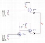
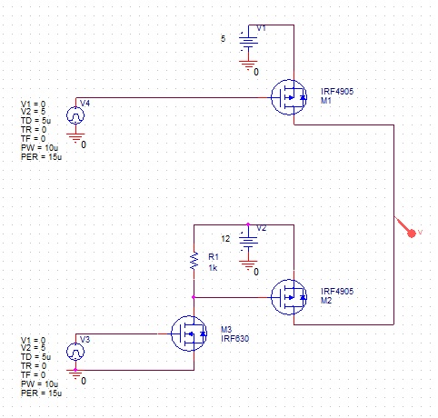
I need to give pulses of above mentioned voltages on one line. Of course, at different times. For example, 2us I need the voltage to be 5V, then 2us 12V, and then 2us it goes to 7V. For now, I am trying to get 12V and 5V levels working. All this is to be driven by a MCU pin, which is 5V. This makes it the simplest thing for 5V level, but at 12V it gets a bit more complicated. For some reason, even though I get fine on/off pulses at the gate of the 12V-PMOS, it's drain never gives me 12V. Vds voltage goes up to 4 or 5V...

Why is this happening? Is my approach wrong?

If you would need me to upload the project file or the simulation results, just let me know. I am using this MOS because we have those in the lab... :)

Thank you.

86_1318371405.jpg
 

It doesn't work this way, because the M1 reverse diode won't allow an output voltage above 5.6 V. You'll need true bidirectional switches for the lower voltage levels, e.g. back-to-back connected MOSFETs. You didn't mentioned load impedance respectively intended output currents, so exact suggestions aren't feasible now.
 

Note that when the lower side mosfet M2 turns on it will provide 12v to the drain of the upper mosfet M1 so the diode will conduct and short the 12v with the 5v

Alex
 
  • Like
Reactions: logicon

    logicon

    Points: 2
    Helpful Answer Positive Rating
Without going into details, the concept is good, just separate both switches (or at least the 12V side) with diodes, see attached picture ..
:wink:
IanP
 

Attachments

  • 2 x switch2 --- 12-10-2011.JPG
    2 x switch2 --- 12-10-2011.JPG
    33.6 KB · Views: 89
Just separate both switches (or at least the 12V side) with diodes.
This will work fine, if "give pulses" doesn't mean the capability to generate negative transients and if analog accuracy isn't an issue. If one or the other is an objective, than any kind of bidirectional analog switch would be required.
 

Thank you all.

In my simulation diodes work just fine. This is only the input of a bit more complicated circuit, so I will get back to you if I face some problems because of this. That is why I will mark this as solved.

As far as output load is concerned, there will be another level of MOSFETs and then the CAN bus. The device that I am working with for some reason needs 7V and 12V pulse to start, and afterwards it communicates using good old CAN. So, this input circuit is only a voltage level selector for a CAN controller.

Thank you.
 

Status
Not open for further replies.

Part and Inventory Search

Welcome to EDABoard.com

Sponsor

Back
Top