Continue to Site

Welcome to EDAboard.com

Welcome to our site! EDAboard.com is an international Electronics Discussion Forum focused on EDA software, circuits, schematics, books, theory, papers, asic, pld, 8051, DSP, Network, RF, Analog Design, PCB, Service Manuals... and a whole lot more! To participate you need to register. Registration is free. Click here to register now.

Pulse Current PCB width calculator

Status
Not open for further replies.

penrico

Full Member level 5
Joined
Aug 28, 2001
Messages
285
Helped
27
Reputation
54
Reaction score
8
Trophy points
1,298
Location
Argentina
Activity points
2,393
Hey,

I have a board that have some signals, that will have non repetitive pulses of 8A 20 mSeg long.
The problem, is that my board don't have enoght space to use a 150 mils or more to meet the 8A current in average mode.

Do somebody has a I2t (current vs time) formula for the widht of trace in PCB?. Do somebody has something of information how to calculate the right trace width for a pulse current?

Thanks.
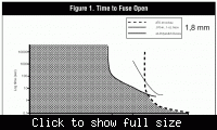
 

As a conservative estimation, you can put in the copper foil thermal capacity and a permissible overtemperature to calculate an I2t value.
I remember, that Raychem had published some I2t data of PCBs related to fuse dimensioning.


    penrico

    Points: 2
    Helpful Answer Positive Rating
If you are in doubt, can you increase the thickness of the copper layers? This normally doesn't take more board space.

Can you just use a thinner track locally, and use a wide enough trace where possible? IMHO you can live safely with less than half of the 150mils for a single 20msec pulse.

Stefaan
 

From thermnal capacity, I calculate a Δt of 1.4 K for a 75 mils 1oz (35 um) trace. With 15 mils, Δt for a single pulse is below 40 K.
Resistive voltage drop and average power dissipation may be a more serious problem.
 

Status
Not open for further replies.

Part and Inventory Search

Welcome to EDABoard.com

Sponsor

Back
Top