Continue to Site

Welcome to EDAboard.com

Welcome to our site! EDAboard.com is an international Electronics Discussion Forum focused on EDA software, circuits, schematics, books, theory, papers, asic, pld, 8051, DSP, Network, RF, Analog Design, PCB, Service Manuals... and a whole lot more! To participate you need to register. Registration is free. Click here to register now.

pull up and pull down transistor

Status
Not open for further replies.

preethi19

Full Member level 5
Joined
Jun 30, 2014
Messages
273
Helped
0
Reputation
0
Reaction score
1
Trophy points
16
Activity points
3,474
Hi i am trying to learn the concept of pull up and pull down transistor. I found this concept online which is described below. When two current sources (Transistors which act as current sources) are connected in series, determination of the output voltage is done. I have attached an image with rough values (just for eg i used random voltages and current resistor values). Pls correct me if my understanding is wrong!!!
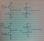
image.png

In (1) we can see equal currents of 3A flow through both the resistors and we find the Vout value.

In (2) for decreased gate voltage at pmos and increased gate voltage at nmos the current values changes and so does the Vout.

All this is fine. I read here the transistors act as pull up and pull down meaning that they "force an output or input to go to a desired state".

So say i want 6V at nmos gate again which is now increased to 6.4V. How does this happen. Like how does the circuit correct back to the state in (1) from (2). Can anyone plsssss explain this concept with simple math??? If there is a feedback then wer is the feedback connection given and from der on wat happens and how does the calculation go becoz i would like to solve it and see. Would be a great help.. Thank you!!!!
 
Last edited:
This resembles the output stage of an op amp. It must solve a similar calculation. It forces the output to a certain voltage. It does this, whatever the resistance of the load, and whatever voltage is coming from the other end of the load.

The decision-making circuitry needs to be able to decide which transistor to turn on, and how much to turn it on. It is wasteful to have upper and lower transistors both on simultaneously (a condition known as 'shoot-through'). It's hard to figure out whether the decision is a function of voltage regulation, or current regulation.

Many internal schematics have a current mirror in one of the middle stages, which governs the output somehow.
 
Hi,

You say "current sources" but calculate as they are resistors.

When a true high side current source of 2.8A meets a low side current source (sink) of 3.2A, then the output is completely low= 0V.
It is far away from being 6.4V.

If there is a load, then the curcuit tries to sink 0.4A. It only depends on the load what voltage there will be at the output.

Klaus
 
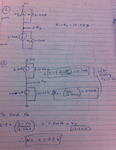
Thank you both so much for the reply!!! Yes i am sorry i calculated using resistors. I have attached an image of an example i was taught since that would be more clear i guess.
image.png

In (1) we can see the current sources are the same. In (2) the current source below increased to 1mA. Say for eg the gate voltage of nmos (below current source is 1V). I was taught that wen the gate voltage of nmos increases for eg by 0.1V (like 1V+0.1V) then the current source also increased from 0.8mA to 1mA which is shown in (2). I am able to understand how to calculate Vd. But as Brad replied "it forces the output to a certain voltage" and "the decision making circuitry needs to decide which transistor to turn on how much to turn on". Could you kindly explain this step pls. Like Is der any method with the feeback and how we give the feedback and how to calculate from der on which shows and brings back the result to 0.8mA. Like with simple intuitive math. If der is any book also i am willing to have a look at it if you could suggest me it. I am in my basics level so material that explains in steps. Thank again!!! Really appreciate the help!!! :)
 
Last edited:

Hi,

With true current sources. Without resistors.
It only depends on the load what voltage there will be at the output.
What is your load?

With the two shown 12k5 resistors:
The equivalentto tbe resistors is:
* like they are in parallel: --> 6.25k
* like the resulting resistor is connected to 5V/2 = 2.5V
* voltage across resistor = R x I = R x (I1 - I2)

Klaus
 

Status
Not open for further replies.

Similar threads

Part and Inventory Search

Welcome to EDABoard.com

Sponsor

Back
Top