Engineer4ever
Member level 3

- Joined
- Feb 2, 2013
- Messages
- 67
- Helped
- 1
- Reputation
- 2
- Reaction score
- 1
- Trophy points
- 1,288
- Activity points
- 1,748
Hi,
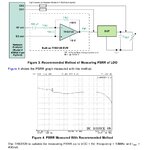
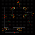
I am designing an error amplifier as a part of LDO circuit and I needed to get its PSRR. I placed an AC source as a power supply with a swing=1v and freq=1KHz. When I put DC voltage=3.5v in the AC source, the PSRR graph was completely wrong, it was improving as freq. increases!!!! When I put DC voltage=zero, the graph was right, PSRR value was getting worse as freq. increases.
The question is, is it right to put DC voltage=zero? because I didn't know that and I was just trying different ways to fix the problem and I thought that the DC value of power supply should be kept during this analysis.
Thanks,


