Continue to Site

Welcome to EDAboard.com

Welcome to our site! EDAboard.com is an international Electronics Discussion Forum focused on EDA software, circuits, schematics, books, theory, papers, asic, pld, 8051, DSP, Network, RF, Analog Design, PCB, Service Manuals... and a whole lot more! To participate you need to register. Registration is free. Click here to register now.

[SOLVED] PSpice Transformer high current problem

Status
Not open for further replies.

af19

Newbie level 4
Joined
May 7, 2017
Messages
6
Helped
0
Reputation
0
Reaction score
0
Trophy points
1
Activity points
58
Hello guys.
I have a very strange problem in PSpice.
I was going to use a transformer in PSpice, and I created a simple circuit to test the transformer.
Output voltage of the transformer was correct but when I measured current of the source, it was about 50 KA peak to peak!!
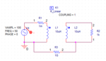
The circuit is so simple, there is only a VSIN, a transfromer and a 1K Resistor in the output as a load.

I tried everything I knew. I used XFRM_LINEAR as the transformer, I used K_LINEAR and two inductors but nothing solved my problem.

I am struggling with this issue about 5 days.

I am using Cadence OrCAD 17.2.

Does anyone have a suggestion?
This problem is making me crazy:|:|

Here is the Circuit and the Current waveform.
 

Attachments

  • circuit.PNG
    circuit.PNG
    6.5 KB · Views: 130
  • Current.PNG
    Current.PNG
    23.6 KB · Views: 122

I used XFRM_LINEAR as the transformer, I used K_LINEAR and two inductors but nothing solved my problem.
100/(2*pi*50*10*10^-6)=31.831 kA ≈peak current .. expectable to see those high currents.

If you want a transformer, use XFRM_linear and take care of the inductances of the primary and secondary of the transformer. N1/N2=√(L1/L2) , so adjust inductances according to your desired turn ratio. Be aware that big inductance leads to less current. If you want less current, increase the inductance !

- - - Updated - - -

By the way, XFRM_linear = ideal transformer + magnetizing inductance... just do not be too surprised if you see the source "sourcing" current when heaving the secondary open... it is just the magnetizing current.
 

100/(2*pi*50*10*10^-6)=31.831 kA ≈peak current .. expectable to see those high currents.
Thanks for the reply.
I think this formula is correct when the secondary is short circuit.
But there is a 1K resistor in the output.
And when I measure the secondary current it is 100mA (100v/1k) which is correct, but the primary is around 50KA.
How is it possible?
 

And when I measure the secondary current it is 100mA (100v/1k) which is correct, but the primary is around 50KA.
How is it possible?

Perhaps if you change coupling factor from 1 to some realistic value, the simulation would behave differently, I guess.
 

I think this formula is correct when the secondary is short circuit.
No. If short circuit at the secondary, then theoretically current is infinity.
But there is a 1K resistor in the output.
And when I measure the secondary current it is 100mA (100v/1k) which is correct, but the primary is around 50KA.
How is it possible?
It is possible because the simulator is working exactly as expected. Read post #2 again.

Please do the following:
1) Take XFRM_linear and set the secondary with open circuit (or place a 1 T resistor.. or diodes back to back.. whatever)
2) Measure the source current.

Do you expect "0" current or something else?
If your answer is 0 , then you do not understand how the transformer works.
 
Last edited:

Do you expect "0" current or something else?
.
Thanks for your reply.
I don't expect zero current.
But at no load test, primary current of the transformer is equal to it's magnetizing current.
As we know, Xm value of transformers are very big, so the magnetizing current should not be a big value.
But in this circuit the no load current is in order of KA. Is this current something other than Magnetizing current?
How we can know what is the value of Xm in XFRM_linear? Is it the 10uH value?
Am I missing a point?
I really appreciate your help.
 

But in this circuit the no load current is in order of KA. Is this current something other than Magnetizing current?
Neglecting those 10 mA, those kA are exactly the magnetizing current.
How we can know what is the value of Xm in XFRM_linear? Is it the 10uH value?
Yes, Lm = 10 uH in your case.

You are the one to set the magnetizing inductance of the transformer. It can be 10 uH or any value you want... double click the XFRM_linear part (or open its properties) and set its inductance values on L1 and L2. Remember N1/N2=√(L1/L2).

Depending on what side of the transformer you are looking from, with other words, you are taking as input i.e. setting the input voltage source to that side, the magnetizing inductance will be exactly the inductance of that side.
For example, if you are taking the primary as input, then L1=Lmagnetizing inductance and hence Vin/XL will be the magnetizing current (neglecting any other voltage drop on that mili ohm resistor you set in series with the ideal voltage source).
If you are seeing it from the other side i.e. placing the input source to the secondary side, L2=Lmagnetizing inductance ... no one cares from which side a transformer is seen...
 
Last edited:

As we know, Xm value of transformers are very big, so the magnetizing current should not be a big value.
Xm of real 50 Hz transformers is in fact. Do you know that Xm = ω Lm? Why no select a reasonable Lm value, e.g. 1 - 10 H instead of 10 µH?
 

Status
Not open for further replies.

Similar threads

Part and Inventory Search

Welcome to EDABoard.com

Sponsor

Back
Top