Continue to Site

Welcome to EDAboard.com

Welcome to our site! EDAboard.com is an international Electronics Discussion Forum focused on EDA software, circuits, schematics, books, theory, papers, asic, pld, 8051, DSP, Network, RF, Analog Design, PCB, Service Manuals... and a whole lot more! To participate you need to register. Registration is free. Click here to register now.

Proximity switch not working

Status
Not open for further replies.

jowin

Newbie level 3
Joined
Apr 7, 2012
Messages
3
Helped
0
Reputation
0
Reaction score
0
Trophy points
1,281
Activity points
1,303
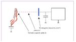
I have built the proximity switch circuit in extreme circuits **broken link removed** but the circuit doesnt make noise only when the sensor terminal is grounded and when I connect the sensor end to a metal object it makes sound but when I connect the ground to the the metal object it doesn’t sound and also when I touch the metal when the ground terminal is connected to it.. It doesn’t make a sound.. My question is how to make the metal sensor for this circuit???
Proximity Switchw.gif
 

First of all, you need to specify what type of sensor are you looking for. That’s not a metal sensor, it was designed to detect when an object nears the sensing surface it enters the electrostatic field of the electrodes and changes the capacitance in an oscillator circuit (IC1A). As a result, the oscillator begins oscillating.
The oscillation is then rectified by D1 and the IC1B circuit reads the oscillator’s amplitude and when it reaches a specific level the output state of the IC1B changes. As the target moves away from the sensor the oscillator’s amplitude decreases, switching the IC1B output back to its original state.

The sensing surface of a capacitive sensor is formed usually by a plate (that’s not connected to the GND or other metallic objects) and a for a good result larger sensing area is recommended.
 

Attachments

  • sensor proximity.png
    sensor proximity.png
    94 KB · Views: 80

I would rather expect the oscillation to be stopped by hand effect. But I'm not able to clearly determine an expectable output state in this situation. In fear, it's simply a case of bad design.

In addition, I would expect instructions how to adjust the potentiometers. Are there any? The posted link doesn't refer to a design.
 

Thanks for the help mister_rf and fvm The link for the circuit which has the instructions I have pasted doesn't seem to have pasted correctly.. This is the correct link. **broken link removed** ......... The design of mister_rf is working!!... :) ...... But the circuit is making sound in alternate push pull manner... Please tell me how to adjust the potentiometer in the circuit...
 

Status
Not open for further replies.

Part and Inventory Search

Welcome to EDABoard.com

Sponsor

Back
Top