Continue to Site

Welcome to EDAboard.com

Welcome to our site! EDAboard.com is an international Electronics Discussion Forum focused on EDA software, circuits, schematics, books, theory, papers, asic, pld, 8051, DSP, Network, RF, Analog Design, PCB, Service Manuals... and a whole lot more! To participate you need to register. Registration is free. Click here to register now.

[SOLVED] Proteus Simulator and PIC16F1825 CLKOUT

Status
Not open for further replies.

victoramas

Junior Member level 1
Joined
Jun 19, 2006
Messages
16
Helped
0
Reputation
0
Reaction score
0
Trophy points
1,281
Activity points
1,478
I have tested it with PIC16F1825 at 32MHz internal clock.
At CLKOUT pin, OSC2, PORTA, RA4 it suppose to come a rectangular signal with a frequency Fosc/4=8MHz and is not there, the virtual digital oscilloscope does not show it.
I have tested the same HEX code on a real PIC16F1825 and I measured it with a real oscilloscope and I can see the 8MHz CLKOUT signal.
With Proteus I cannot simulate CLKOUT.
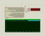
I asked directly on Proteus forum and the say is working and they provided the screenshot below, but without virtual oscilloscope and without showing how they did it, what setup and what code was used and they locked the question.
Any idea how they did it?
 

Attachments

  • clockout.jpg
    clockout.jpg
    140.7 KB · Views: 224

with a frequency Fosc/4=8MHz and is not there, the virtual digital oscilloscope does not show it.

Do you mean, you can't see anything there ? The waveform is incorrect ? Whitout seeing how did you configure your oscilloscope, it is impossible to determine the reason of that. By the way, keep in mind that in general it takes few seconds prior to display the waveform, apparently because simulator need to gather a minimum amount of samples, sincerely don't know why.
 

If you use 8 MHz Crystal with 4x PLL then in Proteus MCU properties you have to still mention 8MHz for the MCU Click. You should not mention 32MHz.
 

@Okada
I do not use the external crystal. I use the internal clock with oscillator set at 8MHz+PLL and I get 32MHz as Fosc.

@andre_teprom
I see nothing there, no signal and Proteus runs for 2min continuously. Then I tried instead of oscilloscope to use the timer/counter and probe+digital graph and nothing.
That puzzles me, even more.
How did the guys from Proteus forum do it? The screenshot from my question is not mine; it is from Proteus technical support.
I have tried 3 compilers with different settings and no result. I have tried 3 more different simulators and no result.
The main software used is not important, can be just a simple on/off LED blink for one pin, another than RA4.
With the real device there is no problem.
Can you test it in a simulator?
 

I would recommend you show a snapshot of the general configuration panel of the microcontroller in Proteus schematic capture sheet, just double-click over PIC16F1825 device, to see what are the FUSE settings.
 

Before I will show you the screenshots from Proteus, I think is better to look at the main Configuration Bits in Configuration Word 1 and Word 2 as appear in the C project.
Because I have tried with several compilers, let’s focus now on one. Below is the MPLABX with C code for XC8 compiler.
The code used is:
Code:
#include <xc.h>
#include <pic16f1825.h>
#define _XTAL_FREQ  32000000

// CONFIG1
#pragma config FOSC = INTOSC    // Oscillator Selection (INTOSC oscillator: I/O function on CLKIN pin)
#pragma config WDTE = OFF       // Watchdog Timer Enable (WDT disabled)
#pragma config PWRTE = OFF      // Power-up Timer Enable (PWRT disabled)
#pragma config MCLRE = OFF      // MCLR Pin Function Select (MCLR/VPP pin function is digital input)
#pragma config CP = OFF         // Flash Program Memory Code Protection (Program memory code protection is disabled)
#pragma config CPD = OFF        // Data Memory Code Protection (Data memory code protection is disabled)
#pragma config BOREN = ON       // Brown-out Reset Enable (Brown-out Reset enabled)
#pragma config CLKOUTEN = ON    // Clock Out Enable (CLKOUT function is enabled on the CLKOUT pin)
#pragma config IESO = OFF       // Internal/External Switchover (Internal/External Switchover mode is disabled)
#pragma config FCMEN = OFF      // Fail-Safe Clock Monitor Enable (Fail-Safe Clock Monitor is disabled)

// CONFIG2
#pragma config WRT = OFF        // Flash Memory Self-Write Protection (Write protection off)
#pragma config PLLEN = ON       // PLL Enable (4x PLL enabled)
#pragma config STVREN = OFF     // Stack Overflow/Underflow Reset Enable (Stack Overflow or Underflow will not cause a Reset)
#pragma config BORV = LO        // Brown-out Reset Voltage Selection (Brown-out Reset Voltage (Vbor), low trip point selected.)
#pragma config LVP = OFF        // Low-Voltage Programming Enable (High-voltage on MCLR/VPP must be used for programming)


void main(){
    OSCCON = 0xF0;
    OSCSTAT = 0x00;
    OSCTUNE = 0x00;
    
    LATA = 0b00000000;    
    TRISA = 0b00101110;    
    ANSELA = 0x00;
    WPUA = 0b00101110;
    IOCAP = 0x00;
    IOCAN = 0x00;
    IOCAF = 0x00;
    APFCON0 = 0x00;
    APFCON1 = 0x00;
    
    while(1){
    LATA0=1;
    __delay_us(100);
    LATA0=0;
    __delay_us(100);     
    }
}

Now let’s focus on the Configuration Bits, because something is strange.
Configuration Word 1 has address 0x8007 and Configuration Word 2 has the address 0x8008.

If I go in MPLABX-Windows- Pic Memory Views-Configuration Bits I get for Configuration Word 1 the value 0xC7A4 and for Configuration Word 2 the value DDFF.
If I open the MPLAB CODE CONFIGURATOR plugin then I get for CONFIG1 the value 0x17A4 and for CONFIG2 the value 0x283
If I open the datasheet of PIC16F1825 and I set on paper each bit, then I get:
1) Configuration Word 1:
Bit13 - FCMEN = 0
Bit12 - IESO = 0
Bit11 - !CLKOUTEN = 0
Bit10-9 - BOREN<1:0> = 11
Bt8 - !CPD = 1
Bit7 - ! CP = 1
Bit6 - MCLRE = 0
Bit5 - ! PWRTE = 1
Bit4-3 - WDTE<1:0> = 00
Bit2-0 - FOSC<2:0> = 100
Then CONFIG1 = 00011110100100 = 0x7A4

2) Configuration Word 2:
Bit13 - LVP = 0
Bit12 - !DEBUG = 1
Bit11 - Unimplemented = 1
Bit10 - BORV = 1
Bit9 - STVREN = 0
Bit8 - PLLEN = 1
Bit7-5 - Unimplemented = 111
Bit4 – Reserved = 1
Bit3-2 - Unimplemented = 11
Bit1-0 - WRT<1:0> = 11
Then CONFIG2 = 01110111111111 = 0x1DFF

Now I already have a problem.
The Configuration Bits done by hand on paper match the last 3 digits of the Configuration Bits done by MPLABX as 7A4 and DFF, but there is 4th digit is different. And the MPLAB CODE CONFIGURATOR plugin is even worse, maybe is using a mask when the final code is generated, because not all the bits are mentioned.
You asked me what kind of Configuration Bits I used in Proteus.
I tried all, starting by “Default” and then all the values above.
I trusted more the values done by hand on paper, because they were also confirmed by FlowCode program as in the attached screenshot.
Here is a link with different screenshots and if more is needed I can provide more:

https://goo.gl/yoqKBb
 

I have not tried this processor in Proteus, but on other processors if you want the Clkout to be modeled you have to right click on the processor select properties to get the Edit component box select advanced properties and select clkout on the drop down menu and select enable. Note enabling the clkout will slow down the simulation. If this option is not present for this processor then this function is not modeled.
 
@pjmelect
It did not cross to my mind to look there.
You found the solution.
Thank you very much.
 

Status
Not open for further replies.

Similar threads

Part and Inventory Search

Welcome to EDABoard.com

Sponsor

Back
Top