Continue to Site

Welcome to EDAboard.com

Welcome to our site! EDAboard.com is an international Electronics Discussion Forum focused on EDA software, circuits, schematics, books, theory, papers, asic, pld, 8051, DSP, Network, RF, Analog Design, PCB, Service Manuals... and a whole lot more! To participate you need to register. Registration is free. Click here to register now.

Proteus PIC port setting problem (complex)

Status
Not open for further replies.

pjmelect

Advanced Member level 2
Joined
May 13, 2012
Messages
576
Helped
127
Reputation
254
Reaction score
131
Trophy points
1,323
Visit site
Activity points
5,891
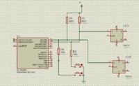
The attached file contains a very simple Proteus circuit and program with a problem that has had me stumped for some time now. All the program does is write some data to a port and read it back in again in a loop checking the results. Every so often the wrong data is read from the port if any analogue component is connected to the port such as the virtual scope or a resistor. The program works correctly in hardware but not in Proteus. I am at a loss as to how to correct this as this is not a programming problem but a simulator bug. Any suggestions as to any settings in the simulator that may make my program run correctly?
 

Attachments

  • TEST2.rar
    12.2 KB · Views: 127

Use shadow registers. When you do BSF or BCF it reads port current voltages, sets or clears bits, and sets new output values. When you do BSF or BCF in series like this:

BSF PORTA,0
BCF PORTA,2
And there are some capacitance on pin, it may be that bit 0 at PORTA has not yet hit high level when it is readed by BCF command. And this way it is read as 0 and stored as 0 by next command.

Use RAM register to store state of PORTA and manipulate bits there. Copy RAM register value to PORTA when done.


Oops. Sorry, read your post wrong, you did say this works at hardware. Maybe my answer is still worth checking out?
 
The program and circuit I attached I wrote as a simple example of the problem.

When you do BSF or BCF in series like this:

BSF PORTA,0
BCF PORTA,2
And there are some capacitance on pin, it may be that bit 0 at PORTA has not yet hit high level when it is readed by BCF command. And this way it is read as 0 and stored as 0 by next command.

Yes I understand this, it is why I added the nop's in the program. I think that the problem is caused by a metastability issue in the Proteus model of the PIC port, but would like others opinion on this.

Edit The example program I posted does not have the nop's between the bsf and bcf, but if you add them it makes no difference.
 
Last edited:

Try changing oscilloscope to digital type and see if it works. PRIMITIVE=DIGITAL in edit properties.
I used the scope as an example of a analogue device, in my actual circuit I use resistors on the port pin which cause the same problem.
 

The circuit and code I originally posted was a simplified example to show the problem, here is the actual circuit (still very much simplified)


As I said the circuit and code works on the hardware, its just that I can't get it to work reliably on Proteus. On the real circuit I use the port pins for multiple inputs and outputs, if I didn't not even a 16F877 would have enough port pins.
 

Hi pjmelect;
You're right, it's a really interesting problem. I played a bit with your above project and found the issue what you have written. After lots of NOP were added (see new asm file), was finally eliminated the error (even with two new analog resistance, even the clock is also 8 MHz). Run the new DSN and see the Watch window, the newly added error counters do not increasing (remain zero). Do not ask me why and how, but I'm sure that the "Simulator Options" menu should / could change something. The reason is otherwise known, it is called RMW (Read-Modify-Write) problem of the PIC16 non-enhanced family (no LATx register).
Sorry, no more time, but I hope this also will help you.
zuisti
 

Attachments

  • Test_8.zip
    14 KB · Views: 88
Thank you for your post zuistii. I thought that it was a interesting problem as well and I have spent more time on this than I should have. Strangely the number of nop's required is not constant and the amount of time required before the problem occurs is also variable. You can make this effect much worse by changing the rise and fall times of the port outputs, try 5nS. What is happening I think is the read modify write cycle when you write to the ports is occurring at digital speeds, but when a analogue device is connected, the port output is changing at a much slower rate causing the read modify write cycle to read the incorrect value for the port pin previously written. This is a error in the Proteus simulation of a port pin. It is impractical to put so many nop's in my program and the program works on the hardware without them. I am still looking for a better solution, if anybody knows of any simulator settings that may help with this.
 
Last edited:

HI, PJMELECT

I looked at you problem and yes interesting.
It seems that the PROTUES simulator is not very good at
Simulating mixed digital and analogue circuits
However there is a work round for this which
I have found. In you circuited posted if you place
Resistors (Defined as digital), in series with both
input of the oscilloscope you will find that the circuit
works OK. The value of the resistor is un-important
in the simulation.

I have had this problem before with mixed circuits
and the offending analogue components had
to be excluded from the simulation otherwise the time
taken to simulate digital/analogue node becomes very
long and the simulator is found to crash out.
 
Status
Not open for further replies.

Similar threads

Part and Inventory Search

Welcome to EDABoard.com

Sponsor

Back
Top