Continue to Site

Welcome to EDAboard.com

Welcome to our site! EDAboard.com is an international Electronics Discussion Forum focused on EDA software, circuits, schematics, books, theory, papers, asic, pld, 8051, DSP, Network, RF, Analog Design, PCB, Service Manuals... and a whole lot more! To participate you need to register. Registration is free. Click here to register now.

Proteus LED MATRIX design

Status
Not open for further replies.

cuber18

Advanced Member level 4
Joined
Sep 4, 2010
Messages
109
Helped
10
Reputation
20
Reaction score
9
Trophy points
1,298
Activity points
1,937
i have my led matrix desing in proteus isis.. 7 rows and 40 columns.. i have 74hh154 in my rows and 74hc595 with my columns.. i completed and function it properly.. it is scrolling.. then i attach 7 TIP147 in my rows for current issues.. i connect the TIP147( which is PNP) emitter to VCC then simulated it.. no scrolling is done.. then i tested a single 5x7 led matrix, connecting one of the 7pins to VCC and one of the 5 pins to gnd.. there is no input.. i was confused because i thought my design rows is positive and my columns are negative.. because in my simulation the row pins are red in color which is positive and 40columns are blue which is negative.. so how do i implement it in actual? which is which?


rows = anode and columns = cathode
or
rows = cathode and columns = anode?
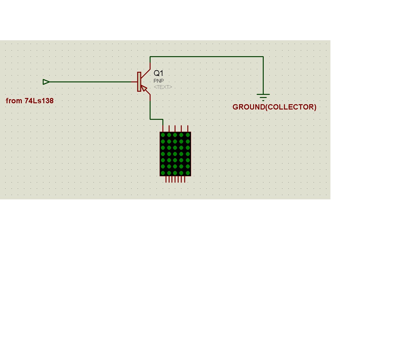
 

heres the complete documents of my project, hope you can help me on this... thanks
 

Attachments

  • Using microPIC.rar
    103 KB · Views: 629
  • Like
Reactions: hessam

    hessam

    Points: 2
    Helpful Answer Positive Rating
74hc154 has a LOW active output, you were driving the rows with GND.
To work you have to connect the collector of your PNP to the GND and the emitter to the rows, drive the base from the 74hc154 (on with LOW).
Note that for 0v input in the base the emitter output will be 0.7v.
You also need to use a resistor in the base or emitter to limit the current to the leds (in a real design)

Alex
 
Last edited:
74hc154 has a LOW active output, you were driving the rows with GND.
To work you have to connect the collector of your PNP to the GND and the emitter to the rows, drive the base from the 74hc154 (on with LOW).
Note that for 5v input in the base the emitter output will be 4.3v.
You also need to use a resistor in the base or emitter to limit the current to the leds (in a real design)

Alex

so for my actual design what it should be with this kind of connection? rows = anode and columns = cathode?so for my actual design what it should be with this kind of connection? rows = anode and columns = cathode?

is it ok for my rows which is anode to have pnp transistor? if it is my PNP collector to gnd and emitter to 5v?
 

The connection can be done as shown in the image. But put resistors at the base of the transistor

 
The connection can be done as shown in the image. But put resistors at the base of the transistor


and btw im not using and 5x7 module.. i will make 7x40 led matrix manually.. so what is my row? and my column? should i let my row to cathode or my row to anode? in my design in isis..

---------- Post added at 14:28 ---------- Previous post was at 14:23 ----------

**broken link removed**
heres my design and its working fine.. is this ok if i will implement to actual hardware?
 

The output of 74hc595 is 1(high), so better use it for column i.e., make your columns anode. Otherwise you have to invert the outputs of 74hc595 IC and it will increase hardware size and cost, as there will be 40 lines from 74hc595 ic.

---------- Post added at 19:01 ---------- Previous post was at 18:59 ----------

**broken link removed**
heres my design and its working fine.. is this ok if i will implement to actual hardware?

Still would say that you should put a small value resistor at the base of each transistor for protection.
 
The output of 74hc595 is 1(high), so better use it for column i.e., make your columns anode. Otherwise you have to invert the outputs of 74hc595 IC and it will increase hardware size and cost, as there will be 40 lines from 74hc595 ic.

yes i am using 74hc595 in my columns.. didnt you see in my documents? :)) in my schematic what transistor array should i couple with it? a NPN transistor? and for my 74hc154 PNP transistor?

---------- Post added at 14:35 ---------- Previous post was at 14:34 ----------

The output of 74hc595 is 1(high), so better use it for column i.e., make your columns anode. Otherwise you have to invert the outputs of 74hc595 IC and it will increase hardware size and cost, as there will be 40 lines from 74hc595 ic.

---------- Post added at 19:01 ---------- Previous post was at 18:59 ----------


Still would say that you should put a small value resistor at the base of each transistor for protection.

yes sir im aware of it.. thank you sir..
 

rather than going for transistors use ICs like ULN 2003 they are inbuilt darlington pairs
 
uln 2003 will not cause any problem to your circuit. You can go through the datasheet of uln 2003 ic.
 

uln 2003 will not cause any problem to your circuit. You can go through the datasheet of uln 2003 ic.
but uln2003 has ony 7 outputs.. what uln that have 8 outputs? and can sink my matrix's current?
 

Use multiple uln2003 ics.

and can sink my matrix's current?

uln 2003 can source as well as sink current. Because normally we use uln 2003 ics for dc motors also. So don't worry about sinking and sourcing current.

---------- Post added at 19:31 ---------- Previous post was at 19:30 ----------

Use multiple uln2003 ics.

and can sink my matrix's current?

uln 2003 can source as well as sink current. Because normally we use uln 2003 ics for dc motors also. So don't worry about sinking and sourcing current.
 
Use multiple uln2003 ics.


uln 2003 can source as well as sink current. Because normally we use uln 2003 ics for dc motors also. So don't worry about sinking and sourcing current.

---------- Post added at 19:31 ---------- Previous post was at 19:30 ----------

Use multiple uln2003 ics.


uln 2003 can source as well as sink current. Because normally we use uln 2003 ics for dc motors also. So don't worry about sinking and sourcing current.

i apply your uln2003 to my 74hc595 but i have no output.. the output of the uln2003 is in logic level low.. :(
 

uln 2003 can source as well as sink current. Because normally we use uln 2003 ics for dc motors also. So don't worry about sinking and sourcing current.

No, ULN2003 can only SINK , it is an open collector output.
You use it in a motor with the other side of the motor connected to the positive supply so when ULN is on it sinks the current and the motor works.

Alex
 
No, ULN2003 can only SINK , it is an open collector output.
You use it in a motor with the other side of the motor connected to the positive supply so when ULN is on it sinks the current and the motor works.

Alex


sir alexan have you downloded my design.. is my design, row=cathodes?
 
Yes your design has rows =cathode and column=anode.

I don't know why but everything i have tried with your design doesn't work, very strange.
The PNP emitter follower should have worked, I don't know if its the simulation model or if I'm doing something wrong.

Alex
 

Status
Not open for further replies.

Part and Inventory Search

Welcome to EDABoard.com

Sponsor

Back
Top