Continue to Site

Welcome to EDAboard.com

Welcome to our site! EDAboard.com is an international Electronics Discussion Forum focused on EDA software, circuits, schematics, books, theory, papers, asic, pld, 8051, DSP, Network, RF, Analog Design, PCB, Service Manuals... and a whole lot more! To participate you need to register. Registration is free. Click here to register now.

proteus 741 op amp current to voltage converter

Status
Not open for further replies.

gc627

Newbie
Joined
May 4, 2021
Messages
3
Helped
0
Reputation
0
Reaction score
0
Trophy points
1
Activity points
38
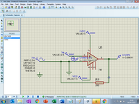
i know the basics of an op amp with just the negative and positive input and one output , using a resistor Rf it will stop the current flowing in to the inputs and instead convert it into a voltage at Vout

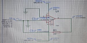
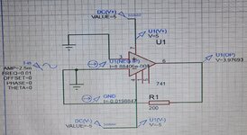
the supply is a ac current in the range of -2.5 to 2.5 mA with an frequency of 0.01 Hz and output is 2 to 3v
Rf = VoMax -VoMin /IinMax -IinMin = 3v - 2v / 0.0025A - -0.0025A = 200 ohms


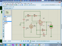
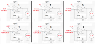
so i know the 741 needs a supply voltage of up to 15 v to operate ,why does the supply voltage of pins 4 and 7 affect the output ?


ive looked all over for examples but the ones i see have just a positive and negative unknown value at pins , if anyone has any links explaining this it would be greatly appreciated

so one attempt is saying 3.97 v and even when i remove the ac source from the circuit and resimulate it doesn't change anything therefore it hasn't converting current to begin with ?
 

Attachments

  • 741 test.jpg
    741 test.jpg
    2.6 MB · Views: 299
  • 741 test 2.jpg
    741 test 2.jpg
    681.8 KB · Views: 442
Last edited:

Hi,

,why does the supply voltage of pins 4 and 7 affect the output ?
Does it?
I can´t verify this on your screenshots. (please in future use the screenshot feature instead of photos)

in your schematic both the inputs are GNDed. This can´t work. It just short circuits the AC input.

Klaus
 
Last edited:
ok i have updated my circuit however , as you can see current is flowing into the terminal of the op amp when it should be going to the resistor

G
 

Attachments

  • new idea.png
    new idea.png
    102.1 KB · Views: 276

Hi,

--> remove the GND at the inverting input.

and read some basic OPAMP circuit stuff.

Klaus
 

get national semiconductor application note 31

or the "newer" version from texas instruments

op amps are not passive devices like resistors and capacitors
they require power, provided by the power pins, 4 and 7 for the 741 as you noted in post 1

in general, the power pins do not effect the output
BUT, in general, if you apply insufficient voltage, the signal may be clipped at high voltage or at low voltage, or both.
for example, if you power the op-amp between 0V and 5V, but the output signal
should range beyond that, the signal will be clipped
in addition, there is some overhead in all op-amps - for a 741, you need to read the data sheet,
but i'm guessing about 1.5 V on both the high end and low end, so that the actual
output range is between -13.5V and +13.5V when powered between -15V and +15V
 

AFAIK, the suited way to define supply voltage on Proteus is by defining it on the "power rail configuration" menu, not by injecting a power source straight on the pins.
 

Hi,

--> remove the GND at the inverting input.

and read some basic OPAMP circuit stuff.

Klaus
ok ive completed my circuit, the input corresponds correctly with voltage output i used 2 resistors to achieve 2.5v for pin 3. my final question is what reasoning do i use for choosing them why not say two 470k resistors instead of two 10 k resistors. i plan to run the output through a low pass filter of 50Hz again i know the formula but how do i choose a realistic value for resistor ?
 

Attachments

  • final circuit.png
    final circuit.png
    102.8 KB · Views: 259

what reasoning do i use for choosing them why not say two 470k resistors instead of two 10 k resistors.
* current consumption
* noise
* distortion
* other part values (capacitor values)
* for a filter: cut off frequency

Klaus
 

The input is -2.5mA to +2.5mA and the output must be from 2.0V to 3.0V.
Then the inputs must both have +2.5V of offset.
I posted this in the other two forums:
 

Attachments

  • current to voltage.png
    current to voltage.png
    51 KB · Views: 167

Hi,

Opamp 741 is from 1968 .... and that's what it's performance is.

Some may drive cars from the 1960ies because of their nostalgia...maybe they build some retro car or other devices with that old parts.
Nothing against it.

Everybody knows that there was an improvement with cars in the past 50 years. And it's the same with semiconductors.

I personally can't recommend someone to use that old devices for new designs.

Klaus
 

Did you notice the bulletin says the 741 opamp is 57 years old but other websites say it is 52 years old.
It says the minimum supply is +/-10V but some of them work with "only" +/-5V.
Some old teachers do not know about the advancements in modern opamps.
 

Status
Not open for further replies.

Similar threads

Part and Inventory Search

Welcome to EDABoard.com

Sponsor

Back
Top