narithota
Full Member level 1
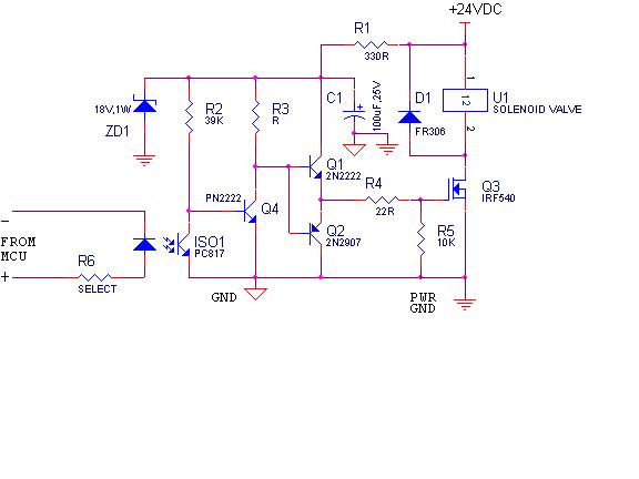
pwm proportional solenoid valve
Hi everybody
I have to control the Proportional solenoid valve (0-24v, 1A) by using 89S51 for flow control according to the feed back signal.
Please suggest some suggestions & information regarding this project
Regards
Nari
Hi everybody
I have to control the Proportional solenoid valve (0-24v, 1A) by using 89S51 for flow control according to the feed back signal.
Please suggest some suggestions & information regarding this project
Regards
Nari