Continue to Site

Welcome to EDAboard.com

Welcome to our site! EDAboard.com is an international Electronics Discussion Forum focused on EDA software, circuits, schematics, books, theory, papers, asic, pld, 8051, DSP, Network, RF, Analog Design, PCB, Service Manuals... and a whole lot more! To participate you need to register. Registration is free. Click here to register now.

proplems with my power supply, helllllllp!!

Status
Not open for further replies.

evilheart

Member level 3
Joined
Sep 3, 2009
Messages
67
Helped
3
Reputation
8
Reaction score
2
Trophy points
1,288
Location
egypt
Activity points
1,955
power supply 0-12 v with 7805

i am working on split power supply (5,12,-5,-12v) , that i am going to use for general purposes,this the proteus schematic and it worked well


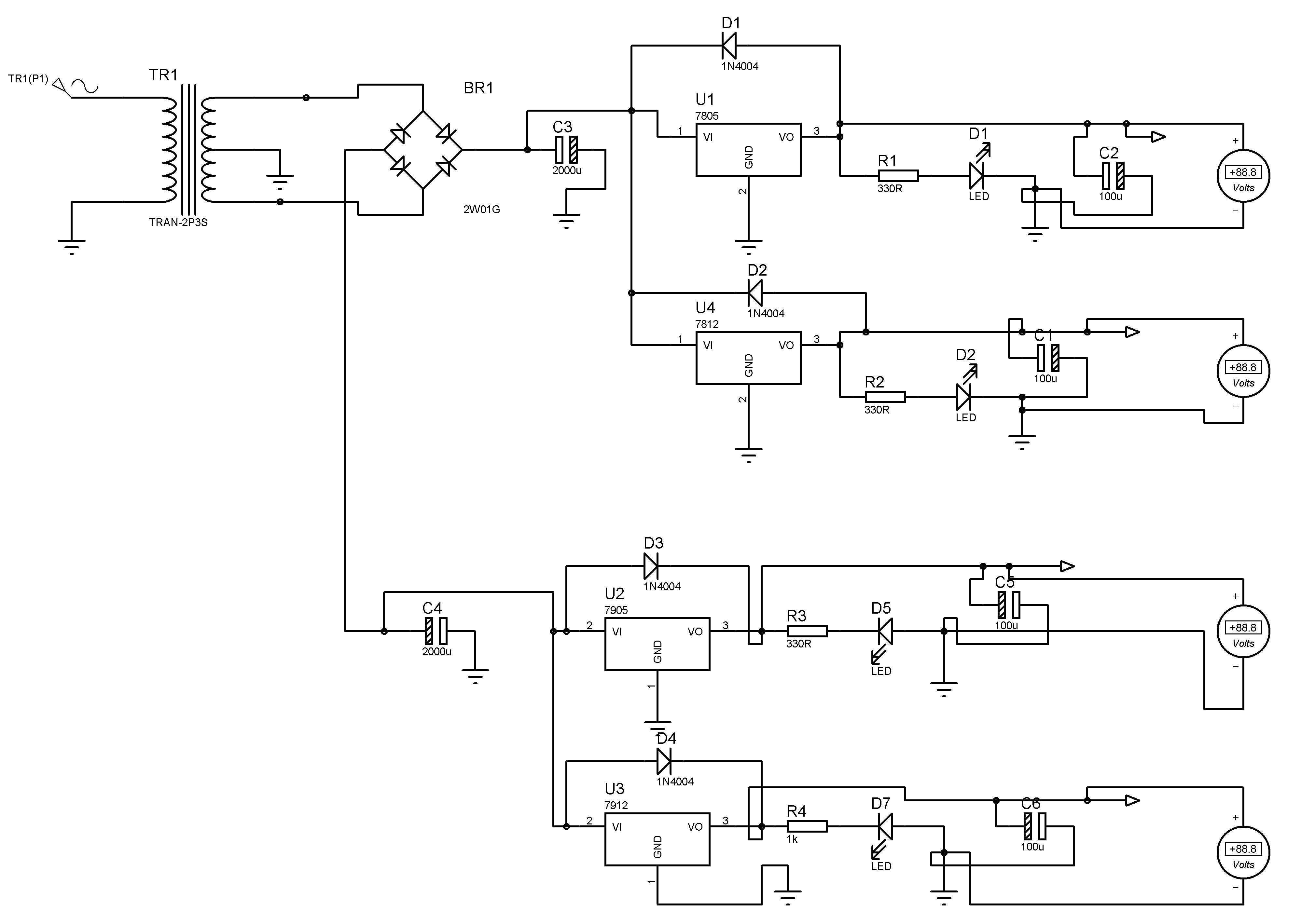
i used 12-0-12 about 1A transformer

2A bridge
7805
7912
2x2200u 16v

for testing the circuit before soldering

i had about 12v on the 7805 o/p and about 0.78v on the 7912
also the 7912 was over heated , i don't know if it is a latch up , and what is its reason if it was a latch up?

and i don't know also why there is that short cct on the 7912 specially and not the 7805 also

that is the second time that problem happens to me and i dont know how to fix it,

please helllllllllp, [/img]
 
Last edited by a moderator:

7905 regulator oscillation

Just a guess, are all the regulator tabs screwed down to the same heat sink?
The negative regulator tabs are connected to the output pin, positive ones to the ground pin.

Brian.
 

7912 regulator oscillating

well i don't use heat sink , that was a first test on the test board with no loads on the regulators , i changed the position of the components to (test) the test board , i changed the regulators but the problem still there.
 

7912 datasheet

evilheart,
Did you check the polarity of the output capacitors connected to the 7912?
Regards,
Kral
 

and the polarity of protection diodes...
 

You have drawn the ac in to the mains transformer one side live the other side earth ?.
It might pay to add some .1uf on the outputs of the regulators just in case they go in to oscillation the 100uf you have might just be to large to dapen them.
 

kral , i think the capacitors will explode if i changed the polarity , any way i didn't use them in my first test

jorgito , i didn't also use diodes at first in my test no problems with that.....

barrybear , i didn't understand ur question , and about the 100u capacitors , can their absence make the 7912 as short cct?

the problem is that the cct i used in my test is quit simple .. transformer + 2 capacitors +2 regulators

but thanks guys for ur help.
 

is this circuit breadboarded?

I'd pull the components and start with the rectifier only, expected voltages?
then I'd triple check the connections and pinouts on regs and ensure 78xx to pos, 79xx to neg. Sounds rediculously simple, but like you said, its a simple circuit. If you have regs non performing, try another as they may have been burnt at some point.
 

yes, i made it on breadboard first ,

without the regulators the rectifier gives about 18 and -18v , after ading the regulators the o/p volt on them becomes about 12~v for 7805 and -0.78 for 7912 it seems that 7912 is making short cct, but i don't know exactly why.

Added after 15 minutes:

and the problem remains even if i changed the regulator , in fact that is the second time to implement this cct and the same problem remained , but it worked on the proteus , it may be potential latch , so any one know how to fix that , or what is its cause?

Added after 4 seconds:

and the problem remains even if i changed the regulator , in fact that is the second time to implement this cct and the same problem remained , but it worked on the proteus , it may be potential latch , so any one know how to fix that , or what is its cause?
 

I would imagine that you did not connect 7912 properly, refer to data sheet for pin-out. It is not the same as positive regulators as already pointed out.
 

Sinisa , the connection of the 7912 is GND-IN-OUT, right? , i feel the problem is that the 7912 is acting as a short cct for some reason ,
thx Sinisa for ur help ,

any one know about potential latch up of regulators , it might be the problem.
 

so then I assume that you have now gone to etched board? I would be inspecting your traces. Maybe consider taking a day off. I find that it helps me when I'm stuck on a ridicously simple problem that for whatever reasons I'm blinded to.
 

Kral said:
evilheart,
Did you check the polarity of the output capacitors connected to the 7912?
Regards,
Kral

As per your circuit the capacitors are reversed

kral , i think the capacitors will explode if i changed the polarity , any way i didn't use them in my first test

It may not if the capacitor rating is too high

Nandhu
 

evilheart said:
Sinisa , the connection of the 7912 is GND-IN-OUT, right? ,
any one know about potential latch up of regulators , it might be the problem.

I don't know of any latch-up problems with voltage regulators.

As far as the pin-out of the voltage regulator, it depends on which packaging you are referring to.

The TO-220 for a National **broken link removed** is GND, IN, OUT left-to-right, when the text is facing you (not the metal tab).

The TO-92 (LM / MC 79L12) is OUT, GND, IN, left-to-right, when the label is facing you.

I suggest adding a fuse on the AC mains side of the transformer. Replacing a transformer is expensive if there is an accidental short, as well as the additional safety.

The power supply capacitors need to be installed correctly, as drawn the polarity is not being consistently observed. Given that they are 100+ uF, these will tend to be polarized electrolytic that can fail / blow themselves up if polarity is not observed.

I believe you have suggested that you have not installed the protection diodes, I suggest not installing until you solve this problem.

I also agree with the idea of trouble shooting one 'section' at a time, for your own sanity. :)

I hope that is of some help, and good luck.
 

Hi,

Cross check maximum input voltage for +ve and -ve regulator with datasheet.

**broken link removed**

you can get the datasheet from above link.

Fro +ve 5V regulator (7805) the maximum input voltage should be 10v it can be extended upto 15v.

To solve this issue, introduce 7812 before 7805.

Take care of terminolagy [(78XX in - gnd - out) and (79XX gnd - in - out)] please refer with datasheet because the terminolagy may vary manufacture to manufacture.

best wishes.
 

thx every one

in fact i used 2200u 25v capacitor , and for the regualtor i/p voltage according to the data sheet ti can handle up to 35-40v < so there is no voltage problems
, i replaced the the regulators with new one with placing diodes on the o/p and GND , and it worked but the 7905,7912 didn't work well after solderind on the PCB.

Added after 3 seconds:
 

If you have built it according to the schematic is should work. There is nothing wrong with the electrical design and the voltages are within limits so the only cause for failure is the construction or layout.

One thing comes to mind, are you observing the rule about wiring lengths to the inputs of the regulators? If more than about 3cm you should add capacitors of 100nF or more directly between the input to ground and the output to ground on ALL the regulators. They should be connected as close to the regulator pins as possible.

I have seen power supplies overheat without any load because the regulators are oscillating. Usually, the output side capacitor also get hot from all the signal forced across it.

Brian.
 

evilheart said:
i had about 12v on the 7805 o/p and about 0.78v on the 7912
also the 7912 was over heated , i don't know if it is a latch up , and what is its reason if it was a latch up?
There is one important thing about negative regulators like 7905, 7912 etc that they are prone to oscillations. The simplest solution is to connect a 0.1 micro farad ceramic across the output of 7905, 7912 etc. I faced similar situations and the issue is resolved.
The 12V output of 7805 is not clear, it may get corrected with this addition of 0.1 uF close to the regulator. (This is missing in your schematic, Please try, I am sure it will resolve -12 problem certainly)
Raoof
 

Brian , Raoof thx alot

that is a good information about the 3 cm distance, the problem i am soldering to a PCB so adding components are not that easy ,but i will keep that in mind, i thought it may be the soldering temperature is the reason because the regulators worked well on the test , and i wasn't using capacitors at the o/p.

Added after 4 seconds:
 

A trick I have used a few times is to solder surface mount capacitors directly across the pins of the regulator just as they leave the plastic package, where the pins are slightly wider. On positive regulators you can fit two capacitors because the ground pin is in the middle but on negative ones you can only fit the one from input to ground. This is the most important one for stability anyway.

Brian.
 

Status
Not open for further replies.

Similar threads

Part and Inventory Search

Welcome to EDABoard.com

Sponsor

Back
Top