Continue to Site

Welcome to EDAboard.com

Welcome to our site! EDAboard.com is an international Electronics Discussion Forum focused on EDA software, circuits, schematics, books, theory, papers, asic, pld, 8051, DSP, Network, RF, Analog Design, PCB, Service Manuals... and a whole lot more! To participate you need to register. Registration is free. Click here to register now.

proplems with my power supply, helllllllp!!

Status
Not open for further replies.
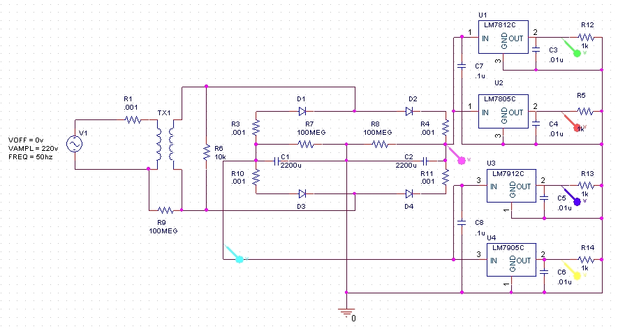
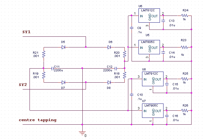
The 0.1 uF at the input side can be ignored as you already have something at that end. Only output side should work. Also, if not otherwise inconvenient it can carefully be mounted on the solder side of the pcb as they are small and the assembly still remains stable.
Raoof
 

I disagree, the output side capacitor will improve transient response and provide filtering for HF getting into the error amplifier through the output pin. It is the input capacitor that is needed for the stability of the regulator itself. It doesn't matter how much capacitance there is in total at the input, it's the impedance that matters. The resistance and inductance of the input wires can cause the impedance to be too high and trigger self oscillation.

Best be safe and put them at both sides though.

Brian.
 

Hi,
Here i give the same thing without centre tapped transformer.

you can use your own transformer, rectifier and 'C' filter as it is.

Just forget about R1,R9,R3,R4,R7,R8,R10 and R11. these are internal resistance and insulation resistance.

Find out below circuit.


Response given below.


you can use centre tapped transformer also.


If you are using any active semiconductor device in your circuit, according to that rating you should provide ceramic (.01u) and electrolite (100u, V>operating V) parallel with device power terminals.


Hope, you are clear.

bye.
 

Senthilkumar.b your second schematic with the centre tapped transformer is the same as Evilheart's original.

Your first schematic might simulate well because it has the same load on the positive and negative outputs but in real life it probably won't work. All the load on one polarity is returned through the other so if they are imbalanced the ground point will no longer be in the middle at 0V.

Brian.
 

In the schematics given by senthilkumar.b all the outputs of regulators are provided with 0.1 uF and not at the inputs individually.
Raoof
 

Change the capacitor values for C7, C8, C9 and C10 in between 220uf to 1000uf according to your load. take care of all electrolyte capacitors polarities.

Sorry for forget to edit these values.

Thanks and bye.
 

thx every one ,

it finally worked .

Added after 5 minutes:

thx every one ,

it finally worked .
 

Is there any R4 = 1K in the circuit shown ?
 

Hi,

In the circuits R18 - R21, R1, R3, R4, R10 and R11 are not physical resistors. that are internal resistors for wire, winding and source.

R9 for insulation impedence in terms of resistance.

R5, R12, R13, R14, R23, R24, R25 and R26 are the resistors for stable operation of Regulators. Regulators are in need of minimum current requirement.

Under no load condition that will failed. to avoid such a situation, those resistors were physically provided. those resistor value varry with respect to the datasheet information.

Bye.
 

Hi, I'm building a power supply with +24V, +5V and +/-12V. I already have a 3 secondary transformer with 22V, 7V and 14-0-14V (peak voltage in these 3 cases). I'm using 7805, 7824, 7812 and 7912 for DC regulation. I was using 47uF in 7824's input, the other regulators's input I've used 10uF capacitors. I've checked also the GND-I-O configuration from the 7912, and used 104 ceramic capacitors besides the input capacitors, and also in the output. 7824 and 7805 are working properly, but I have 0.2V aproximately from 7812 and 1912. Also I've tried adding 1K resistance in the output of each regulator but still doesn't changes. I don't know what else to try! please any suggestions?
 

Status
Not open for further replies.

Similar threads

Part and Inventory Search

Welcome to EDABoard.com

Sponsor

Back
Top