Continue to Site

Welcome to EDAboard.com

Welcome to our site! EDAboard.com is an international Electronics Discussion Forum focused on EDA software, circuits, schematics, books, theory, papers, asic, pld, 8051, DSP, Network, RF, Analog Design, PCB, Service Manuals... and a whole lot more! To participate you need to register. Registration is free. Click here to register now.

Process States with example explanation needs

Status
Not open for further replies.

John99407

Junior Member level 3
Joined
Jul 14, 2019
Messages
26
Helped
0
Reputation
0
Reaction score
0
Trophy points
1
Activity points
240
I have a read bunch of theories on the process state for below picture but still, I don't understand basic. I am looking someone who can help me with example

Task may be waiting to be activated (ready to run), may be running, or blocked (waiting for e.g. some input).

Take example

Task 1 - Read the sensor
Task 2 - display
Task 3 - control Relay

Process: read the temperature and display it value and if the temperature is too high turn off the relay

How would be process diagram for all three tasks

process state.jpg
 

To tell the truth, your diagram resembles a flowchart. However the curved lines really make it look like spaghetti. It's difficult to grasp the overall picture.

In simpler times the priority was to make it easy to follow all interactions.
we drew a flowchart using horizontal and vertical lines. For each step we chose a box shape indicating whether the action was to make a decision, or accept input, or execute output, etc. Group related actions together.

Try to do a similar thing with your sensor/relay sequence. I suppose it starts with 3 boxes, then you break it down into detailed steps as needed.
 
Hi,

Indeed it is not a flowchart but it's a statechart diagram. And it's O.K. the way it is.

For the software - at least for me - it's easier to have a flowchart first.
But with the help of a statechart you know what states you have (use enum to declare the states)
Program step by step what usually happens in the order of "time". Then program all the exceptions.

Klaus
 
To tell the truth, your diagram resembles a flowchart. However the curved lines really make it look like spaghetti. It's difficult to grasp the overall picture.

In simpler times the priority was to make it easy to follow all interactions.
we drew a flowchart using horizontal and vertical lines. For each step we chose a box shape indicating whether the action was to make a decision, or accept input, or execute output, etc. Group related actions together.

Try to do a similar thing with your sensor/relay sequence. I suppose it starts with 3 boxes, then you break it down into detailed steps as needed.
Thanks BradtheRad & Klaus

I am ready to do what you say, but please help me to understand it because I have spent a lot of time to understand this. I found a more theoretical explanation on the google search but I want to understand it with a simple example

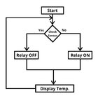
As I was told to make a flow chart I created a simple flow chart I would like you to help me

dia1.jpg
 
Last edited by a moderator:

Your flowchart is an excellent beginning.

Taking another look at your process state diagram, it appears to emphasize input/output protocol. As though a central device must decide the right time to send or receive, based on readiness of another device (or devices).

In like manner we can focus on the many steps of the decision process contained in your diamond-shaped box. I suppose this could be the tie-in to your process state diagram. Your diamond-shaped box could be expanded to several boxes which execute these steps:

* Is sensor ready to send data? If so then poll it.
* Is data usable as is, or does it need to be converted?
* Convert as needed.
* Is temperature reading sufficiently low or high to require action?
Etc.
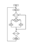
BradtheRad I have done little modification in my flowchart. As you mention the time, I assume that it takes 10 ms to read the sensor and control relay and Display take 100ms time to display the value

Flow Chart 0001.png

Note: I have taken an example of my choice, so no one should feel, Am I not making an effort to learn. If you think the above example is not suitable then you can suggest a better example. I can also work with your example
 

Your example is just fine. I can easily grasp the step-by-step sequence. It's obvious to recognize points of decision-making.

If you were to write program code for a project which does this task, then your flowchart could be the basis for your program's structure. Linear as much as possible but versatile where necessary.

Your process state diagram has several loops. It's not at all linear. I imagine it's a condensed concept of a larger task. If it were drawn as a flowchart it might have sprawling lines and dozens of diamond-shaped decision boxes, each with several choices branching from it.
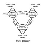
BradtheRad, I hope you don't mind if I change the example. I have come up with a new example, flow chart and state diagram because I think this example is better than the previous

In this example, we have three sensors We send data directly to PC via UART

Read sensor 1 (temperature)
Send data to PC
Receive acknowledge message from PC

Read sensor 2 (humidity)
Send data to PC
Receive acknowledge message from PC

Read sensor 3 (barometer)
Send data to PC
Receive acknowledge message from PC

When sending data to PC, we must indicate to PC that we are expecting response which is received a message

Flow chart: I have shown decision making in the flow chart for communication

Flow Chart 0002.png

Stae machine

State Diagram.JPG

I hope we are making progress to achieve the goal define in starting post
 

Splendid! You're learning by doing. The tasks are similar as sketched in your diagrams, yet one emphasizes a different aspect from the other.

I imagine there are times you want a process state diagram, and other times when you want a flowchart. Suppose you have several processes running simultaneously within a complex system, yet no process is allowed to be a time-hog, or to crash the system. To manage it requires exercising a larger perspective. This might explain multiple occurrences of certain labels in your initial diagram: suspend, wait, resume.
 
Hi,

often it makes sense to use both diagrams at the same time ... especially as beginner it makes sense to draw them (on paper).

In software:
You are in one state ... then on some event you get into another state.
--> IF condition THEN state = x
Example: IF buttonX is pressed THEN (jump to the state to) print the bill
But with the help of the state diagram it's more obvious that in some cases (states) it makes no sense (is not allowed) to print a bill.
--> Example:
In IDLE state (when the user did not yet choose or buy an article) it makes no sense to print a bill.

Later, when you are an experienced programmer, this state diagram may be in your mind and you are used to think about the allowed and not allowed state transitions when you write your code. At least for simple tasks....

Klaus
 
This might explain multiple occurrences of certain labels in your initial diagram: suspend, wait, resume.
@BradtheRad & @KlausST

It has been a long time since I've been trying to compare my diagram with the diagram in post 1 but I am still struggling to understand ready running suspend, wait, states in my example

so far my example I want to make a diagram as shown in the first post but I don't understand how this diagram will be made. Please give me some advice
 

struggling to understand ready running suspend, wait, states in my example

I suspect your initial diagram is a template for a process that has to do with input/output protocols. The terms are generic, non-specific. It's hard to figure out how to apply it because it omits details. We have to guess that the designer understands that the details are present somewhere.

Since you wish to apply it to your sensor-relay project, then we might picture it being one of several processes running in a dedicated operating system. For instance your process might control a room's temperature as one function in a building's heating and cooling system.
 
I suspect your initial diagram is a template for a process that has to do with input/output protocols. The terms are generic, non-specific. It's hard to figure out how to apply it because it omits details. We have to guess that the designer understands that the details are present somewhere.

Since you wish to apply it to your sensor-relay project, then we might picture it being one of several processes running in a dedicated operating system. For instance, your process might control a room's temperature as one function in a building's heating and cooling system.
BradtheRad thank you for the reply. I am trying to understand this for a very long time. I do not understand where I am making the mistake. Is it because of my wrong requirements? if this is the case, would you suggest a good requirement that suits to achieve the goal? I am asking you requirement directly because I have tried to give my best but still I have not got success

Can you provide an example of your choice so that we will find it easier to understand process states ( ready running suspend, wait, ) ?
 
Last edited:

Picture a way for your sensor/relay project to appear in an input/output process (your initial diagram). Perhaps if you were building a system containing more than one sensor or more than one display. Then your flowchart starts to include boxes labelled 'wait', 'resume', etc.

The reason is that you must prevent collisions between the separate routines as they have to cross paths periodically. It's a similar concept to networking, or time-sharing, or multitasking, etc. The process state diagram is kind of an abstraction, portraying events that don't necessarily happen in a particular order.

The 'spaghetti arrows' make allowances for interruptions, long waits for input (for a human to press a button), long waits for output (for a printer to feed paper), etc.

If you start making a flowchart which handles 2 sensors and 1 display, then I believe you'll soon discover what obstacles arise. They're obstacles which are not present with 1 sensor and 1 display.
 

Status
Not open for further replies.

Part and Inventory Search

Welcome to EDABoard.com

Sponsor

Back
Top