Continue to Site

Welcome to EDAboard.com

Welcome to our site! EDAboard.com is an international Electronics Discussion Forum focused on EDA software, circuits, schematics, books, theory, papers, asic, pld, 8051, DSP, Network, RF, Analog Design, PCB, Service Manuals... and a whole lot more! To participate you need to register. Registration is free. Click here to register now.

Process independent current source

Status
Not open for further replies.

Junus2012

Advanced Member level 5
Joined
Jan 9, 2012
Messages
1,552
Helped
47
Reputation
98
Reaction score
53
Trophy points
1,328
Location
Italy
Activity points
15,235
Dear friends,

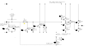
While band gap reference voltage sources provides a reference voltage that is independent of process, voltage and temperature (talking ideally), because the BGR circuits based on resistors ratios with a value that can balance the PTAT to the CTAT voltages.

However, it looks for me that is not possible to have process independent current sources cause the current is always V/R, and R vary with process, unless if we use external off chip resistor which I am not considering.

Please I need you suggestion of process independent current source.
Thank you
Best Regards
 

Trimming is the way to absolute accuracy. Log2(Range/resolution) tells how many bits if it's a discrete (fuse, link) trim method.
 
Thank you Suta for your reply

combining CTAT+PTAT compensate for temperature variation, but process change the resistor value on both of the CTAT and PTAT and hence the total current will be changed.

I have just found this paper work and it mighjt be useful to discuss with you


The author used resistor less beta multiplier circuit as shown in the figure below

current_ref.png


The drain of the transistor M1 will be fixed by the opamp loop so that VDS1 = vref, now if we use bandgap reference voltage which is not sensitive to the process we can get current not sensitive to process as well.

but in this circuit I don't know how he sized the M3 and M4 to accept the Vref that he put, I believe they need to be sized according to the Vref so the difference betwenn VGS2-VGS3= Vref.

Thank you
--- Updated ---

Trimming is the way to absolute accuracy. Log2(Range/resolution) tells how many bits if it's a discrete (fuse, link) trim method.
Thank you freebird for your answer,

I have contacted the foundry and they told me they don't offer laser trimming, this means I have to do the trimming by means of scalable resistors controlled by MOS switches. This is only possible solution if the unit resistor in the array having bigger res than the MOS resistor, on the other hand need big switches.
In the circuit I have designed I used R=2 k Ohm, I am sure that you would agree trimming this value is not possible. If I consider the change on the output of the reference current is only due to the resistor change, then the trimmable resistor must cover +-30%R, means total scalabe 1.2 k Ohm (to cover the range from 2 k-600 to 2 k+600 )
Now take the 1.2 k Ohm and try to make coarse tunning on with only 4 bit ,
1.2 k/16 = 75 Ohm..... quite challenging with 0.35 µm to have a switch that is negligible to this unit resistor.
May be and still valid that we accept the value of the switch as part of the resistor itself, but it will change its temperature behavioral that is important thing for me as I am using the PTAT circuit as temperature sensor

Thanks
 
Last edited:

You can use fuses to control FET switches for a
trim network. Poly fuses are easier to blow than
aluminum. Your foundry may give you a hard time
about reliability if they never qualified a trim
element and its associated programming method.
You might inquire in general terms about support,
and simply not mention fuses if they don't.

You would want to use FET switches with large
value resistors, not small. You can make a small
incremental resistance by putting a low value
resistor in parallel with a switched high value
resistor. For example your 2K resistor could be
a series string of 1K||(10K/switch) and 1K||(20K/switch)
for a network that gives a range from 1.86K to 2K.
That's +/-7% from center (more or less) with about
a 3-4% resolution.


Poly fuse I-V showing forced current of 25mA to open

Poly_fuse_layout.png


Poly fuse layout
--- Updated ---

Fuse trim pad (foundry details obscured) with the fuse
disabled and pad clamp added for pin-controlled
trimming instead, but can be returned to OTP form
by a single mask level change
 

Attachments

  • 1630461073063.png
    1630461073063.png
    50.8 KB · Views: 124

Status
Not open for further replies.

Part and Inventory Search

Welcome to EDABoard.com

Sponsor

Back
Top