Plateau
Junior Member level 3
Hello folks, are you fine?
I am developing a solution to convert the range of the resistence meter of my car's fuel tank to another range because the new dashboard does not work correctly. The original meter works with a range between 0 (empty) and 90(full) Ohms
and the new meter works with a range between 44(full) and 290(empty) Ohms.
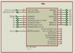
The configuration of 16F876A is:


Using CCs as the compiler, I have created a logic in wich according to the voltage value that was read I set one of the output pins as LOW (output_low) and all of others as FLOAT(output_float) and that's why the PAINEL resistence value (an output in the image above) related to VSS (GND) is 20 Ohms (from PIC) + resistor associated on the pin (example: PIN_A1 -> 20 + 22 Ohms). When I measure the ohm value with a multimeter the value is OK but when I make a voltage divider using a 50 Ohm permanent resistor the voltage value is too wrong, i.e when PAINEL has 263 Ohm in the output and the input voltage of the voltage divider is 10v the resulting voltage is wrong (the correct should be 8.4v but the measured is 6v).
When I simulate in ISIS Proteus this problem does not occur.
Can anybody help me?
Regards,
Pedro Rosa!
I am developing a solution to convert the range of the resistence meter of my car's fuel tank to another range because the new dashboard does not work correctly. The original meter works with a range between 0 (empty) and 90(full) Ohms
and the new meter works with a range between 44(full) and 290(empty) Ohms.
The configuration of 16F876A is:

Using CCs as the compiler, I have created a logic in wich according to the voltage value that was read I set one of the output pins as LOW (output_low) and all of others as FLOAT(output_float) and that's why the PAINEL resistence value (an output in the image above) related to VSS (GND) is 20 Ohms (from PIC) + resistor associated on the pin (example: PIN_A1 -> 20 + 22 Ohms). When I measure the ohm value with a multimeter the value is OK but when I make a voltage divider using a 50 Ohm permanent resistor the voltage value is too wrong, i.e when PAINEL has 263 Ohm in the output and the input voltage of the voltage divider is 10v the resulting voltage is wrong (the correct should be 8.4v but the measured is 6v).
When I simulate in ISIS Proteus this problem does not occur.
Can anybody help me?
Regards,
Pedro Rosa!

