Continue to Site

Welcome to EDAboard.com

Welcome to our site! EDAboard.com is an international Electronics Discussion Forum focused on EDA software, circuits, schematics, books, theory, papers, asic, pld, 8051, DSP, Network, RF, Analog Design, PCB, Service Manuals... and a whole lot more! To participate you need to register. Registration is free. Click here to register now.

Problems with hight frequency noise

Status
Not open for further replies.

Corvuscorax4

Newbie
Joined
Oct 24, 2021
Messages
3
Helped
0
Reputation
0
Reaction score
0
Trophy points
1
Activity points
32
Hi,

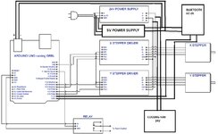
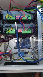
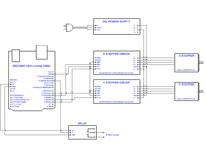
i am making cnc plasma project. Controller crashes and looses steps when plasma cutter is working. I have few questions about grounding and shielding wires maybe somebody who had same experience can help me with advice how to solve my problem. Thank you for any help.
1.Do i need to ground stepper motors?
2.I use shielded wires and putting this wires in to metal corrugated tube. Question is do i need to ground wire shield and metal tube separate or i can connect them to one point. Also do i need to connect it inside metal encloser or outside?
3. Metal encloser and cnc plasma table frame are connected. Do i need to isolate metal encloser from plasma table frame?
4. What grounding system should i use?
 

Hi,

1) I do recommend it. But I doubt it will solve the "missing steps" problem
2) I recoommend to connect shield only at one side of the cable. I recommend to GND the metal tube also at the same side.
3) I don´t recommend to isolate them. But you need to avoid ground loops.
4) For first try: Star grounding.

But indeed these are just raw guessed recommendations. For a better assistance we need to see your whole system.
...maybe upload some photos.

Klaus
i uploaded few photos maybe it will help.
 

Attachments

  • schema1.jpg
    schema1.jpg
    196.8 KB · Views: 144
  • 187403475_314979600003938_8045480782501287180_n.jpg
    187403475_314979600003938_8045480782501287180_n.jpg
    119.1 KB · Views: 133
  • 187357109_290899239357950_1995909333337982867_n.jpg
    187357109_290899239357950_1995909333337982867_n.jpg
    252 KB · Views: 137

Hi,

All wires are mixed...

I recommend...
Mains wires: twist all L and N. Keep them short and away from the low voltage DC wires.
Wire them from input to the first power supply, then to the other power supply.

Low voltage DC wires.
Use a thee terminal distribution block for: GND, 5V and 24V.
Do the 5V wiring in star manner twisted with the according GND. Short.
Do the same with 24V.

Klaus
 

Hi
You need re-wire your system to work properly.
Noise radiated from plasma and its power converter is high and your cable coupling with them.
Controller/Arduino connect directly to PC/Laptop is high risk. If any high voltage > 5V leak from motor driver or other can damage your computer USB port or fully damage it.
Normally good design will not accept direct or extend wire which connect to MCU's pin go out of the PCB. Your system is doing that.
You need add serial resistor to all input/output signal of controller with few K ohm 4.7k 1206, add small xxpF capacitor to filter RF noise, add TVS 5V to absorb surge voltage and protect Controller.
Should isolate UART interface (can apply to USB but more expensive) with core controller (Atmega).
Separate low voltage and high voltage cable as other member said. Don't mix them togather to coupling noise.
If isolated interface, the power supply for controller board need clean enough to ensure controller work properly. Low cost Arduino board use cheap LDO that can't filter high frequency from power supply. You also should add 5V TVS for 5V power supply of the board.
Remember that all input/output signal need high impedance enough to emummen noise, power supply need choke/ LC filter.
I am not very strong in electronics, maybe my questions are dump. Maybe you can mark in my attached scheme how and where i should place resistors? Also i dont use usb cable from controller to computer. I use bluetooth for controlling plasma table. So there is only three wires which are going in to metal box where controller is. 2 wires for steppers and 1 for torch ignition controlling.
 

Attachments

  • 1.png
    1.png
    48.4 KB · Views: 111

It is now clearer that the noise associated with the relay switching is the culprit.

What is the power of the plasma torch? Can you put a high voltage but small value capacitor across the relay contacts? Also put a diode-capacitor snubber across the relay coil.

I guess that will solve the problem.
 

I am not very strong in electronics, maybe my questions are dump. Maybe you can mark in my attached scheme how and where i should place resistors? Also i dont use usb cable from controller to computer. I use bluetooth for controlling plasma table. So there is only three wires which are going in to metal box where controller is. 2 wires for steppers and 1 for torch ignition controlling.

You can try this first ...
1635928740768.png
 

Status
Not open for further replies.

Similar threads

Part and Inventory Search

Welcome to EDABoard.com

Sponsor

Back
Top