Kryptone
Member level 3

- Joined
- Mar 14, 2014
- Messages
- 64
- Helped
- 2
- Reputation
- 4
- Reaction score
- 2
- Trophy points
- 8
- Activity points
- 552
Hello All,
I have been having problems when I connect my boost converter to my h-bridge. The problem I am having is that is when I connect it to h-bridge the indicator leds start to flicker,even screen of my laptop!! then I disconnect and everything goes back to normal. Also, I tried connecting a 75W, 120V bulb to my boost converter output which gives 180Vdc across the capacitor of my LC filter when nothing is connected to it but the voltage drops from 180Vdc to about 3Vdc when the bulb is connected and of course the bulb did not light up and my ferrite core transformer begins to make a noise. What could be wrong???
I am using a 10uF capacitor at the output and I am not sure of the value of the inductor or if it is good. I know that the purpose of the LC filter is to reduce the high switching frequency of 50 kHz to a low frequency in the Hz region as it is a low pass filter. The switching frequency being used in the SPWM section with the h-bridge is 16 kHz
Please Help!!!!!!
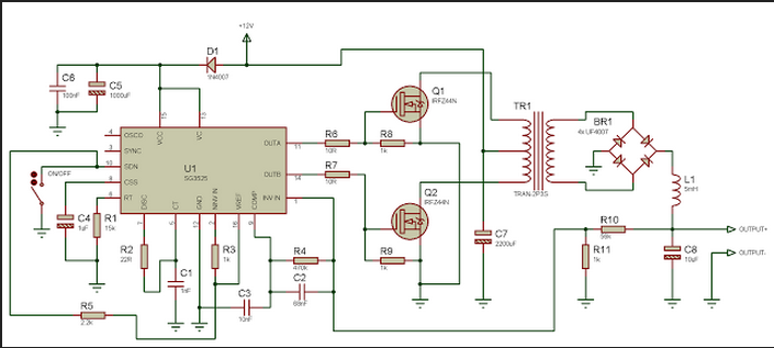
Here is the circuit diagram:
I have been having problems when I connect my boost converter to my h-bridge. The problem I am having is that is when I connect it to h-bridge the indicator leds start to flicker,even screen of my laptop!! then I disconnect and everything goes back to normal. Also, I tried connecting a 75W, 120V bulb to my boost converter output which gives 180Vdc across the capacitor of my LC filter when nothing is connected to it but the voltage drops from 180Vdc to about 3Vdc when the bulb is connected and of course the bulb did not light up and my ferrite core transformer begins to make a noise. What could be wrong???
I am using a 10uF capacitor at the output and I am not sure of the value of the inductor or if it is good. I know that the purpose of the LC filter is to reduce the high switching frequency of 50 kHz to a low frequency in the Hz region as it is a low pass filter. The switching frequency being used in the SPWM section with the h-bridge is 16 kHz
Please Help!!!!!!
Here is the circuit diagram:
Last edited:

