MustaineV
Newbie level 5
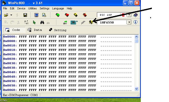
This is the programmer I'm using, it's a JDM Programmer and it comes with a CD with Winpic800 V 3.6 c , one weird thing is how where the arrow is in the manual it shows a right/left switch (dunno what they're called:grin")

Now I put the Pic18f2550 in the programmer, hook it up with a serial cable (F to F, with a gender changer on the Programmer's side) and hook it up, the green LED turns on, I set the type in Winpic and try to write a HEX file to it, (written specifically for it, I might add) nothing. It gives me an error (containing the line 0x000, will screenshot it if that'll help).
Now I admit I'm not good at all with electronics, but this seemed like a simple enough job for me to do. Am I doing something wrong? Or is it a software problem?
Thanks in advance